[0011]In view of the foregoing circumstances, it is an object of the present invention to provide an actuator
control system that can monitor a generic failure and realize redundancy enabling control of the entire operation of a device, from start to finish, when a generic failure has occurred, thus realizing further simplification and streamlining of the configuration, for an actuator control
system in which an actuator control apparatus controls an actuator for driving a device in accordance with a command of an operation control apparatus to operate the device.
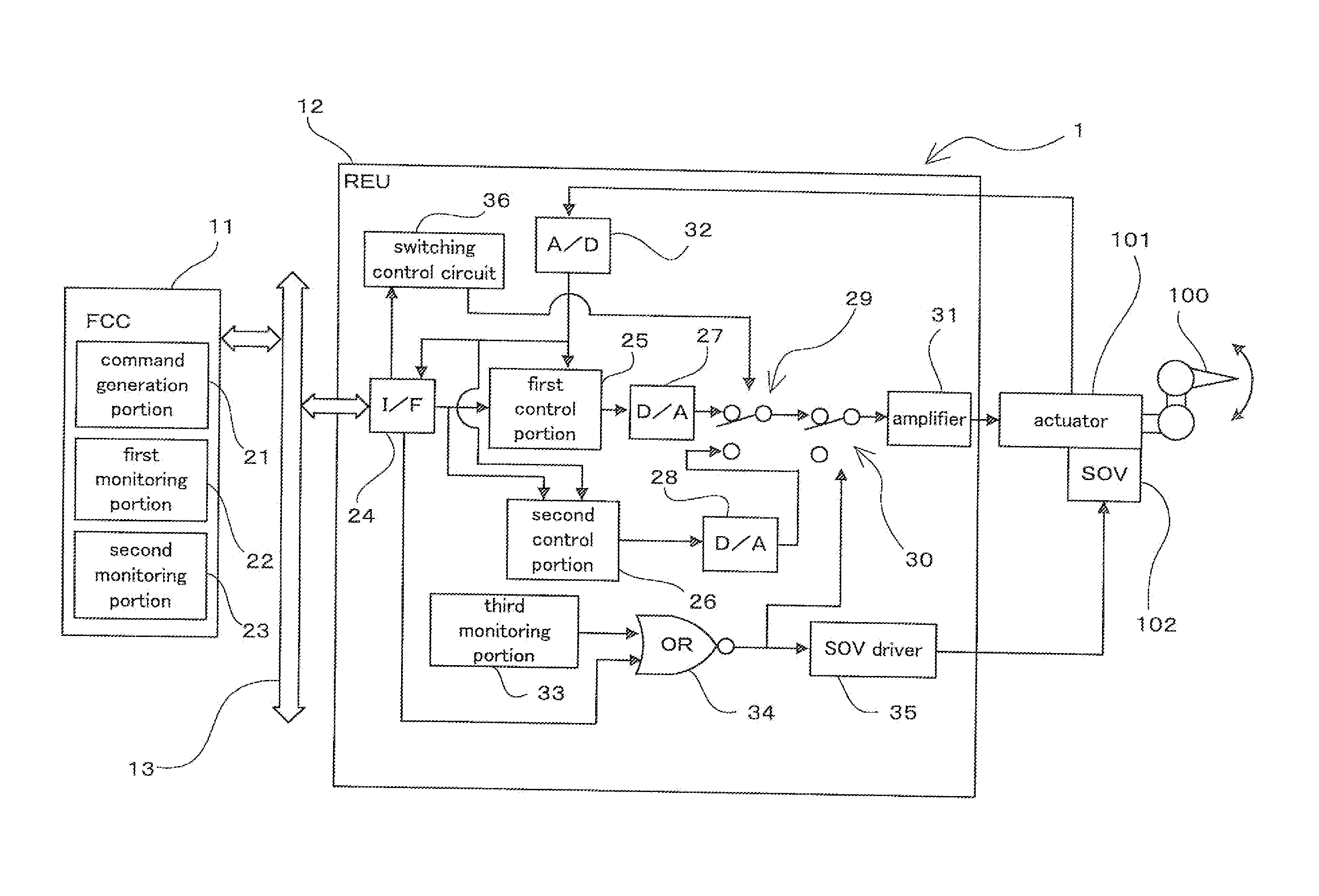
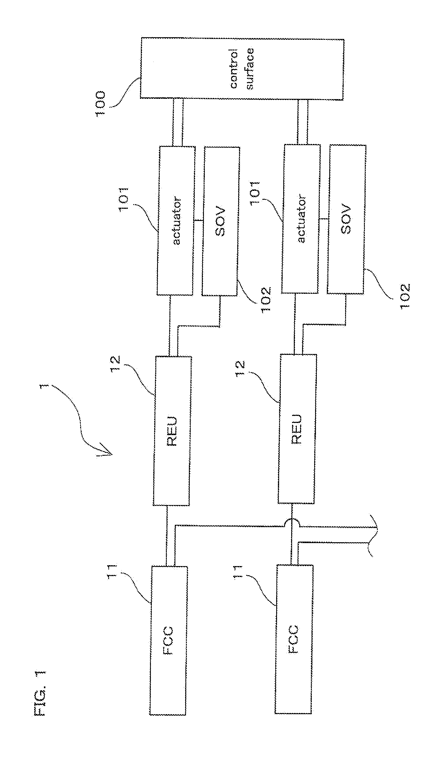
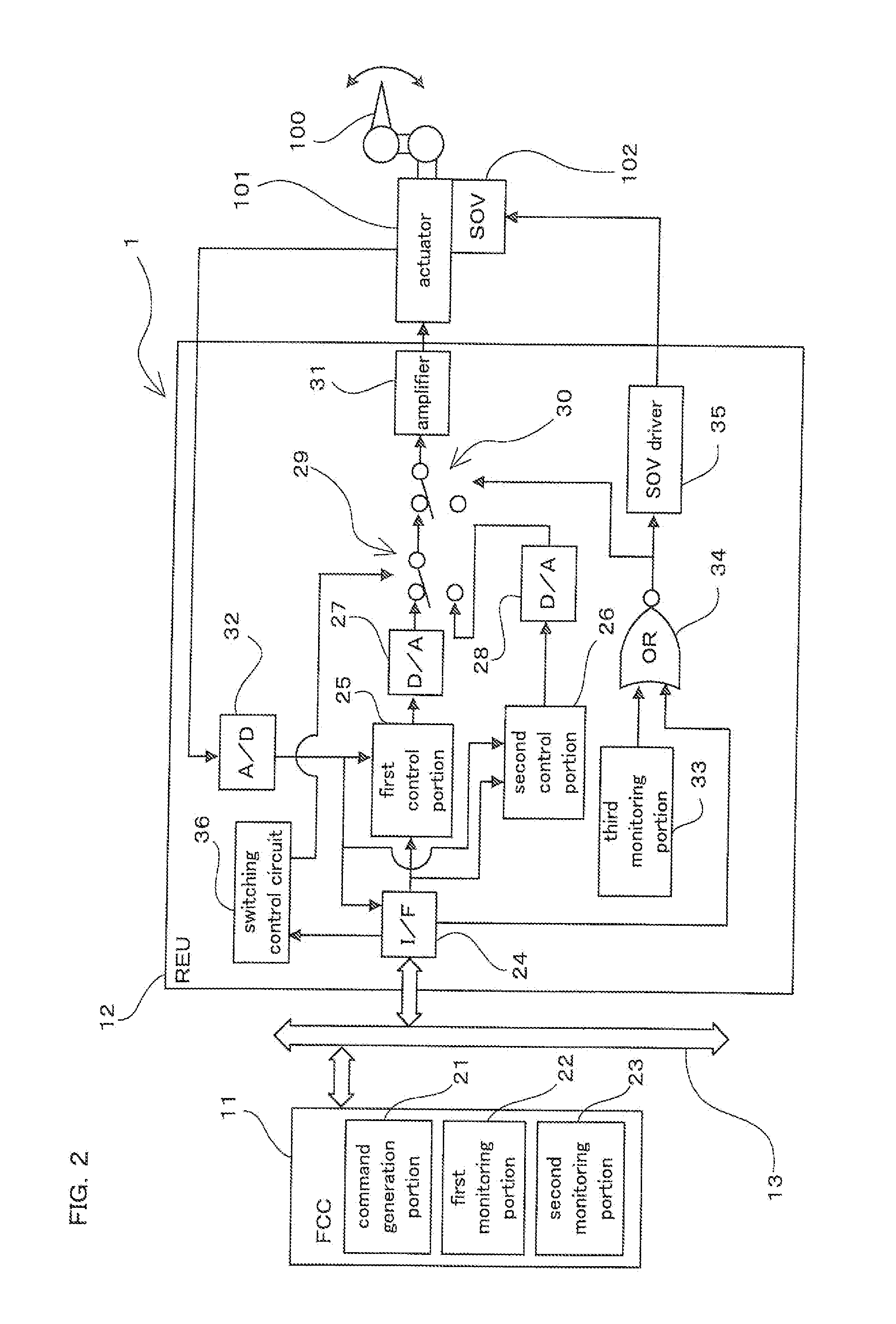
[0013]With this configuration, an abnormality relating to operation of the actuator control apparatus for the processes performed by the first control portion and the second control portion is monitored by the first monitoring portion and the second monitoring portion, making it possible to achieve a configuration that monitors a generic failure. Also, the first control portion and the second control portion are configured to have different designs. When a generic failure has occurred and an abnormality is detected by one of the first monitoring portion and the second monitoring portion, the switching unit switches the connection to the actuator from one of the first and second control portions for which an abnormality is detected to the other. Accordingly, it is possible to realize redundancy enabling control of the entire operation of the device, from start to finish, when a generic failure has occurred. When the actuator control
system having this configuration is provided as an actuator control
system that controls operation of the control surface of an aircraft, it is possible to realize redundancy enabling control of the entire operation of the control surface, including the
takeoff operation of the aircraft, when a generic failure has occurred. Moreover, with the actuator control system having this configuration, the operation control apparatus can be effectively used to
handle the abnormality monitoring functions of the first control portion and the second control portion of the actuator control apparatus, thus reducing the abnormality monitoring functions performed within the actuator control apparatus. This can simplify the configuration of the monitoring portions in the actuator control apparatus in a redundant configuration including two control portions that are different in design, thus realizing simplification and streamlining of the configuration of the actuator control system as a whole.
[0014]Therefore, with this configuration, it is possible to monitor a generic failure and realize redundancy enabling control of the entire operation of a device, from start to finish, when a generic failure has occurred, thus realizing further simplification and streamlining of the configuration, for an actuator control system in which an actuator control apparatus controls an actuator for driving a device in accordance with a command of an operation control apparatus to operate the device.
[0020]With this configuration, abnormalities of operation of the first control portion and the second control portion are monitored by the first monitoring portion and the second monitoring portion on the operation control apparatus side by performing the same processes as the first control portion and the second control portion of the actuator control apparatus, and performing a filtering operation or the like in which the results of the processes are compared. Accordingly, a monitoring target that requires a large computing load such as a filtering operation can be monitored by the first monitoring portion and the second monitoring portion of the operation control apparatus, making it possible to efficiently let the operation control apparatus and the actuator control apparatus to
handle the abnormality monitoring functions in a distributed manner.
[0024]With this configuration, the type of data processed by the first monitoring portion and the second monitoring portion on the operation control apparatus side for abnormality monitoring is set so as to limit the load of the communication data
bus between the operation control apparatus and the actuator control apparatus. Accordingly, the amount of data processed by the first monitoring portion and the second monitoring portion can be optimized from the viewpoint of limiting the data to the type of data that needs to be processed on the operation control apparatus side, and therefore an increase in the load of the data
bus can be suppressed. Although it is also conceivable to use a data
bus capable of high-speed communication, it is possible, with the configuration of the present invention, to efficiently monitor an abnormality with a system that has been realized at a lower cost.
[0026]With this configuration, the data processed by the first monitoring portion and the second monitoring portion on the operation control apparatus side for abnormality monitoring is processed after being divided into the first data that is processed in the predetermined short period and the second data that is processed in the long period. Accordingly, those monitoring targets having high accuracy requirement for
abnormality detection and thus are desired to have a reduced time for
abnormality detection can be processed as the first data, and those monitoring targets having relatively low accuracy requirement for
abnormality detection can be processed as the second data. Accordingly, it is not necessary to uniformly lengthen the communication period of the data bus between the operation control apparatus and the actuator control apparatus, and it is possible to perform
processing in an appropriate period for each of the monitoring targets by effectively utilizing the limited communication period, thus satisfying the accuracy requirement for abnormality detection. Although it is also conceivable to use a data bus capable of high-speed communication, it is possible, with the configuration of the present invention, to efficiently monitor an abnormality with a system that has been realized at a lower cost.


