Multi-utilitarian microcatheter system and method of use

Inactive Publication Date: 2011-10-27
REVERSE MEDICAL CORP
View PDF0 Cites 81 Cited by
  • Summary
  • Abstract
  • Description
  • Claims
  • Application Information

AI Technical Summary

Benefits of technology

[0012]In an embodiment, the micro-catheter can comprise means to deliver therapeutic devices and diagnostic agents through one or more of the catheter's lumens or side holes, which further adds to this systems utility. The devices' lumen, or lumens, could allow for aspiration or drainage.
[0014]The outer diametrically expansile / contractile element, hereafter referred to as the expandable element, which can be generally affixed to the catheter shaft near the distal end of the catheter shaft, can be fabricated from a variety of metallic or polymeric materials, either porous, non-porous, or a combination of these materials. This expandable element can be located within the distal region of the design, but preferably about 3-5 cm from the distal tip to improve guidewire aided navigation through tortuous vasculature. The design is provided with the expandable element it's the most expanded configuration, having an outer diameter of 2 mm to 10 mm, but preferably between 2 mm to 7 mm.
[0015]To contract the expandable element diametrically, a standard 0.010″ diameter guidewire, or other appropriate size, is introduced with the catheter's lumen and one or more lumen constrictions are provided just distal to the expandable element, with an optional constriction positioned proximal to the expandable element. Once the guidewire is positioned through these constrictions, it provides enough frictionally induced axial force on the distal constriction to cause the expandable element to contract in diameter (and expand the element linearly). The guidewire can also increase the bending stiffness of the catheter system. The proximal constriction is useful in maintaining guidewire position and can be advantageous if the guidewire is not otherwise secured at the proximal end of the catheter system. The distal lumen within the element can be provided with a length of helically disposed tubing, a length of serpentine tubing, a biased coil having a central lumen through which a secondary catheter can be inserted, a telescoping tube set, or a bellows mechanism, which provides a corresponding length alteration of the catheter's lumen to coincide with that of the expandable element. The length of the expandable element can be between 10 mm and 50 mm in the outer diametrically expansile configuration and between 12 mm and 100 mm in length in its contractile, minimum diameter configuration.

Problems solved by technology

These disorders are a major cause of morbidity and mortality in the United States.
Failure to re-establish blood flow can lead to the loss of limb, angina pectoris, myocardial infarction, stroke, compromised cognitive or neural function, or even death.
Occlusion of the venous circulation by thrombi leads to blood stasis, which can cause numerous problems.
Additionally, the use of a Fogarty® catheter is problematic because of the great risk of damaging the interior lining of the vessel as the catheter is being withdrawn.
Balloon angioplasty is appropriate for treating vessel stenosis but is not effective for treating acute thromboemboli.
Certain compliant balloons have also been used as temporary neck bridges for coiling cerebrovascular aneurysms with embolic coils or other materials, however the inflated balloons typically block the parent vessel and the patient can only tolerate short-periods, generally inadequate to properly perform embolization of a neurovascular aneurysm, of such ischemic balloon inflation.
Unfortunately, thrombolysis typically takes hours to days to be successful.
Additionally, thrombolytic agents can cause severe hemorrhage and in many patients the agents cannot be used at all.

Method used


Image

  • Multi-utilitarian microcatheter system and method of use
  • Multi-utilitarian microcatheter system and method of use
  • Multi-utilitarian microcatheter system and method of use

Examples


Embodiment Construction

[0048]The inventions disclosed herein may be embodied in other specific forms without departing from its spirit or essential characteristics. The described embodiments are to be considered in all respects only as illustrative and not restrictive. The scope of the inventions is therefore indicated by the appended claims rather than the foregoing description. All changes that come within the meaning and range of equivalency of the claims are to be embraced within their scope.

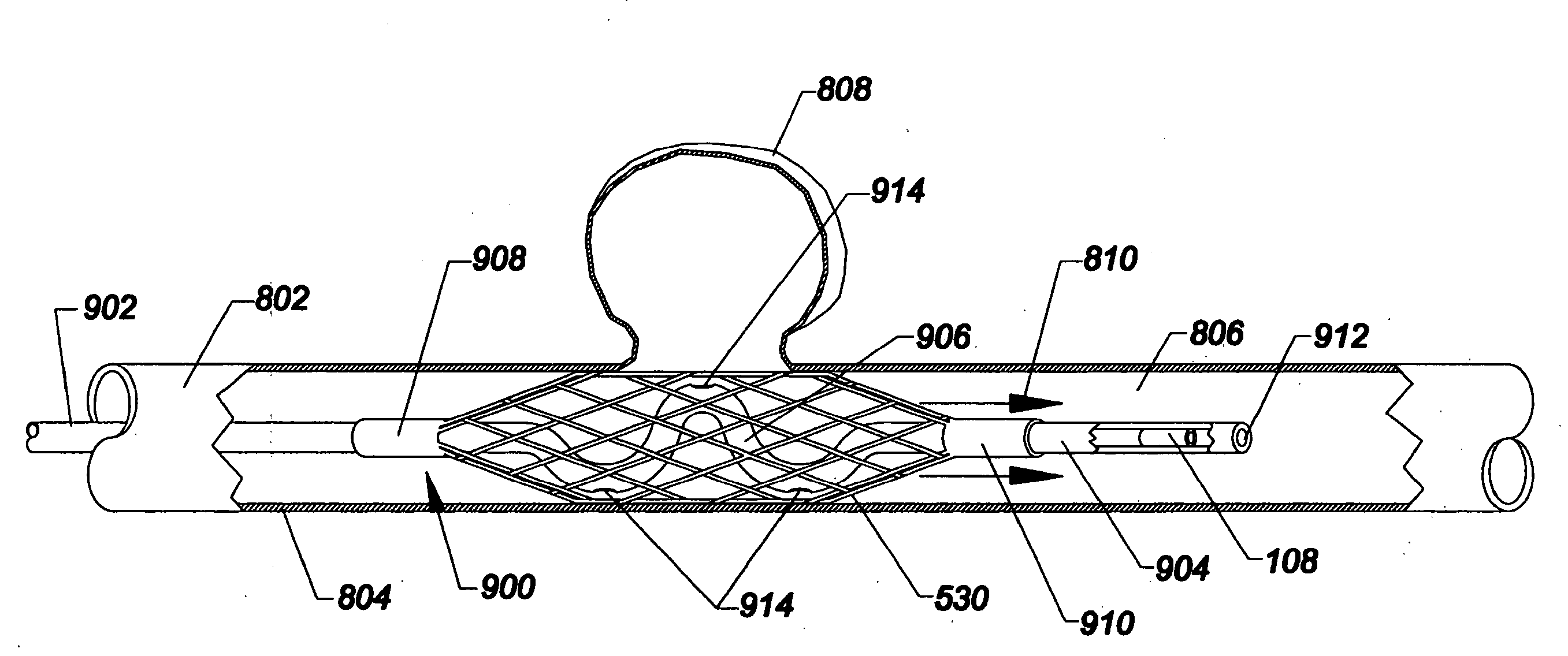
[0049]As used herein, the terms proximal and distal refer to a direction or a position along a longitudinal axis of a catheter or medical instrument. Proximal refers to the end of the catheter or medical instrument closer to the operator, while distal refers to the end of the catheter or medical instrument closer to the patient. For example, a first point is proximal to a second point if it is closer to the operator end of the catheter or medical instrument than the second point. The measurement term French, abbre...


PUM


Abstract

A device for performing therapeutic or diagnostic procedures within the cerebrovasculature includes a catheter having a distal portion, a proximal portion and a lumen extending therebetween, the catheter including an expandable region for engaging the vessel wall, thrombus, atheroma, or other structures. The device further includes an elongate stretching member, which can be a guidewire, insertable longitudinally through the lumen of the catheter, the elongate stretching member being configured for stretching at least a portion of the catheter and causing the expandable region to transition from an expanded state to a collapsed state, and wherein the elongate stretching member is retracted proximally relative to the catheter causes the expandable region to transition from the radially collapsed state to a radially, or laterally expanded state.

Description

RELATED APPLICATION[0001]This patent application claims priority to U.S. Provisional Patent Application No. 61 / 042,687 filed Apr. 4, 2009, the entire disclosure of which is expressly incorporated herein by reference.FIELD OF THE INVENTION[0002]The field of the invention generally relates to devices and methods for protecting cerebral vessels and brain tissue during endovascular treatment. More particularly, the field of the invention pertains to devices and methods for interventional neuroradiology.BACKGROUND OF THE INVENTION[0003]Thromboembolic disorders, such as occlusive stroke, pulmonary embolism, myocardial infarct, peripheral thrombosis, atherosclerosis, and the like, affect many people. These disorders are a major cause of morbidity and mortality in the United States. Thromboembolic events are characterized by an occlusion of a blood vessel. The occlusion can be caused by a clot or thrombus, which can be viscoelastic (jelly-like) and is comprised of platelets, fibrinogen, and...

Claims


Application Information

Patent Timeline
IPC IPC(8): A61M29/00
CPCA61B17/12022A61B17/12118A61B17/1214A61B17/12186A61B17/320725A61B2017/12054A61B2017/22034A61B2017/22045A61B2017/2217A61M2025/0042A61B2017/00336A61B2017/00867
Inventor STRAUSS, BRIAN M.VALKO, JEFFREY J.HENSON, MICHAEL R.
Owner REVERSE MEDICAL CORP
Why Eureka
Try Eureka