Internal Observation Device for Object having Light Scattering Properties, Internal Body Observation Device, Endoscope for Internal Observation and Internal Observation Method
- Summary
- Abstract
- Description
- Claims
- Application Information
AI Technical Summary
Benefits of technology
Problems solved by technology
Method used
Image

Examples
first embodiment
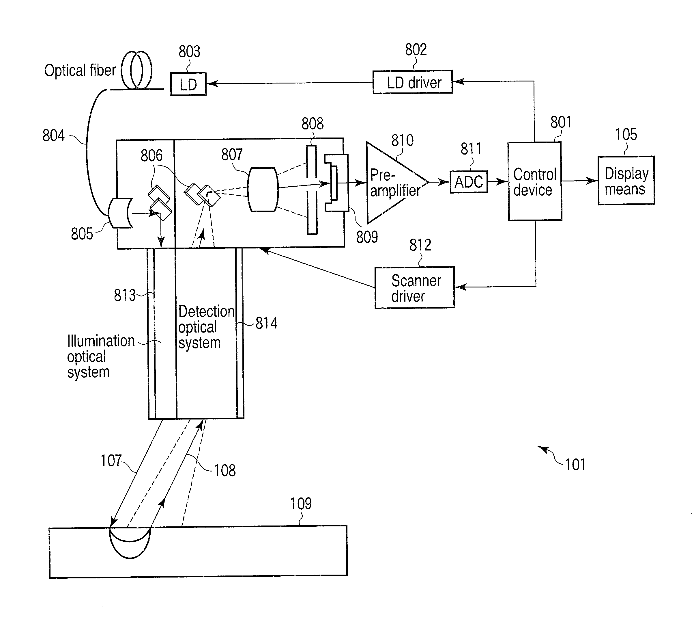
[0082]FIG. 8 shows an example of an apparatus to which a scanning device 501 is assembled.
[0083]A laser light is used as an illumination light, and an illumination device 102 of the laser light comprises an LD 803 and an LD driver 802 for driving the LD 803. The size of an illumination region 201 on a surface of a living tissue 109 can be simply reduced by using the laser light. The illumination light is transmitted by an optical fiber 804 and impinges on scanner mirrors 806 via an NA adjustment optical system 805. The light impinged on the scanner mirrors 806 is irradiated onto the surface of the living tissue 109 via an illumination optical system 813. Since a light outgoing from optical fiber passes via the NA adjustment optical system 805, the light can be converted to an illumination light having a desired NA and a minimized loss, for example, to a parallel light and can be irradiated onto the surface of the living tissue 109.
[0084]A detection device 103 changes a light intensi...
second embodiment
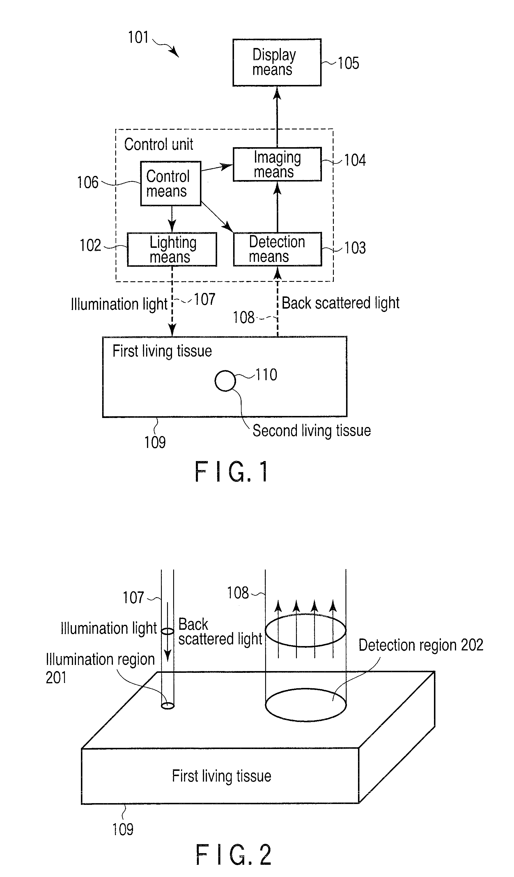
[0089]FIG. 9 shows, as one of embodiments, a block diagram of a configuration in which an illumination light 107 and a back-scattered light 108 are caused to pass via the same optical system.
[0090]The illumination light 107 and the back-scattered light 108 are scanned by a scanning device 902 by disposing a separation optical system 901 on an illumination device 102 side and on a detection device 103 side. A light guide optical system 903 is disposed on the scanning device 902 side, the illumination light 107 is irradiated onto a surface of a first living tissue 109, and the back-scattered light 108 is captured. With the configuration, since each one set of the scanning device and the light guide optical system can be employed, an apparatus can be made compact at a low price.
[0091]FIG. 10 shows a specific configuration of an apparatus to which the separation optical system 901 is assembled. A configuration, which detects only a light outgoing from a detection region 202 by causing t...
third embodiment
[0159]FIG. 14 is a block configuration view of a an apparatus for measuring the interior of turbid media 1401 according to a third embodiment of the invention. As shown in the drawing, the apparatus for measuring the interior of turbid media 1401 includes a movable light irradiation device 1410, a detection device 1411, a control / analysis device 1412, a memory 1413, a display device 1414, and an input device 1415.
[0160]The light irradiation device 1410 is an lighting means which irradiates a light having optical characteristics which differ in an object to be measured 1407 in an inside of a turbid media 1408 and in a scattering medium 1406 in the vicinity of the object to be measured 1407. Although an LD and the like can be used as the light irradiation device, the light irradiation device is not limited thereto. A light having a wavelength, which is absorbed by, for example, an object to be measured but is not absorbed by a scattering medium, may be used as a light irradiated from ...
PUM
 Abstract
Description
Claims
Application Information
 - R&D
- Intellectual Property
- Life Sciences
- Materials
- Tech Scout
- Unparalleled Data Quality
- Higher Quality Content
- 60% Fewer Hallucinations
Browse by: Latest US Patents, China's latest patents, Technical Efficacy Thesaurus, Application Domain, Technology Topic, Popular Technical Reports.
© 2025 PatSnap. All rights reserved.Legal|Privacy policy|Modern Slavery Act Transparency Statement|Sitemap|About US| Contact US: help@patsnap.com