


Quick Research
Generate reliable direction feasibility study reports for your R&D in just a few steps.

Technical Q&A
Discover and master advanced knowledge NOW. Basics, ideas, possibilities, all at once.

Find Solutions
As an expert in R&D theories, this can generate solutions to your technical problems instantly.

Evaluate Feasibility
Analyze your overall solution with one click, know your potential R&D risks in advance.

Monitor Landscape
Get weekly tech updates, stay abreast of the latest tech innovations and key insights.
Electronic product sales display device
A technology for display devices and electronic products, which is applied to display stands, display hangers, display shelves, etc., and can solve problems that cannot be met. The battery is arranged on the right side inside the base, and is electrically connected to the switch through wires; The motor is arranged in the middle part inside the base, and is connected with the rotating disc; the switch is inlaid on the surface of the base, and is electrically connected with the motor through a wire; the rotating disc is arranged on the upper part of the base; The fixed frame structure is welded on the upper part of the rotating disk, etc., so as to achieve good observation and good effect
- Summary
- Abstract
- Description
- Claims
- Application Information
AI Technical Summary
Problems solved by technology
Method used
Image

Examples
Embodiment 1
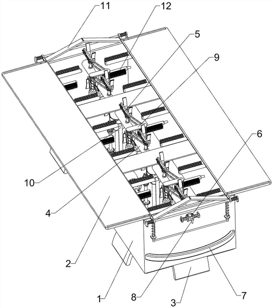
[0026] A sales display device for electronic products, such as Figure 1-2 As shown, it includes a box body 1, a cover plate 2, a support plate 3 and a rotating shaft 4. The cover plate 2 is slidably connected to the left and right sides of the top of the box body 1, and the bottom of the box body 1 is provided with a support plate 3. Inside the box body 1 The upper part is rotatably connected with a rotating shaft 4, and also includes a clamping assembly 5, a limiting assembly 6, a grip bar 7 and a T-shaped bar 8. The rotating shaft 4 is provided with a clamping assembly 5, and a limiting The position component 6 is connected with the handle bar 7 at the bottom of the front and rear sides of the box body 1, and the limit component 6 is provided with a T-shaped bar 8.
[0027] The clamping assembly 5 includes a connecting rod 51, a side plate 52, a splint 53, a guide rod 54 and a pressure spring 55. A plurality of connecting rods 51 are evenly spaced on both sides of the rotat...
Embodiment 2
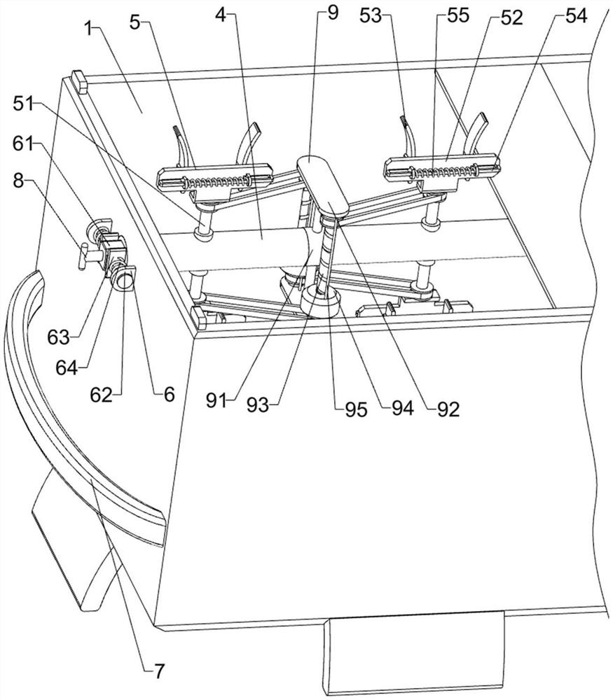
[0032] On the basis of Example 1, such as figure 2 As shown, a transmission assembly 9 is also included, and the transmission assembly 9 includes a central axis rod 91, a horizontal plate 92, a screw rod 93, a gravity block 94 and a vertical rod 95, and three central axis rods 91 are evenly spaced on the rotating shaft 4. Shafts 91 are set at the front, middle and rear. The top and bottom of the central shaft 91 are connected with horizontal plates 92. Both sides of the two horizontal plates 92 are rotatably connected with screw rods 93, and the screw rods 93 are connected with gravity blocks 94 through threads. , are connected with vertical rod 95 between two horizontal plates 92 both sides, two vertical rods 95 are slidably matched with two gravity blocks 94 respectively, and screw rod 93 is connected with the transmission shaft transmission of side plate 52.
[0033] The rotating shaft 4 drives the central axis rod 91 to rotate together when rotating. After the rotating sh...
Embodiment 3
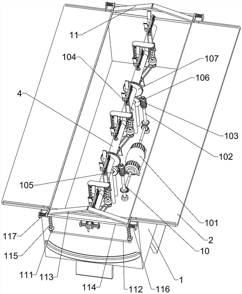
[0037] On the basis of Example 2, such as image 3 As shown, a push assembly 11 is also included, and the push assembly 11 includes a sleeve 111, a U-shaped bar 112, a tapered plate 113, a connecting slide bar 114, a return spring 115, a tension spring 116 and a push rod 117, and the front and back of the box body 1 Sleeves 111 are connected to the left and right sides of the two sides, U-shaped rods 112 are slidably connected between the sleeves 111 on both sides, and a tapered plate 113 is connected to the top of the U-shaped rods 112. There is a return spring 115 connected between them, and connecting sliders 114 are connected to the front and rear sides of the box body 1, and both sides of the connecting slider 114 are slidingly connected to push rods 117, and the two push rods 117 are respectively connected to the cover plates 2 on both sides. A tension spring 116 is connected between the push rod 117 and the connecting slide rod 114, and the conical plate 113 cooperates ...
PUM
 Abstract
Description
Claims
Application Information
 - R&D Engineer
- R&D Manager
- IP Professional
- Industry Leading Data Capabilities
- Powerful AI technology
- Patent DNA Extraction
Browse by: Latest US Patents, China's latest patents, Technical Efficacy Thesaurus, Application Domain, Technology Topic, Popular Technical Reports.
© 2024 PatSnap. All rights reserved.Legal|Privacy policy|Modern Slavery Act Transparency Statement|Sitemap|About US| Contact US: help@patsnap.com