
Driver circuit for driving a print head of an inkjet printer

Inactive Publication Date: 2011-10-27
OCE TECH
View PDF4 Cites 4 Cited by
  • Summary
  • Abstract
  • Description
  • Claims
  • Application Information

AI Technical Summary

Benefits of technology

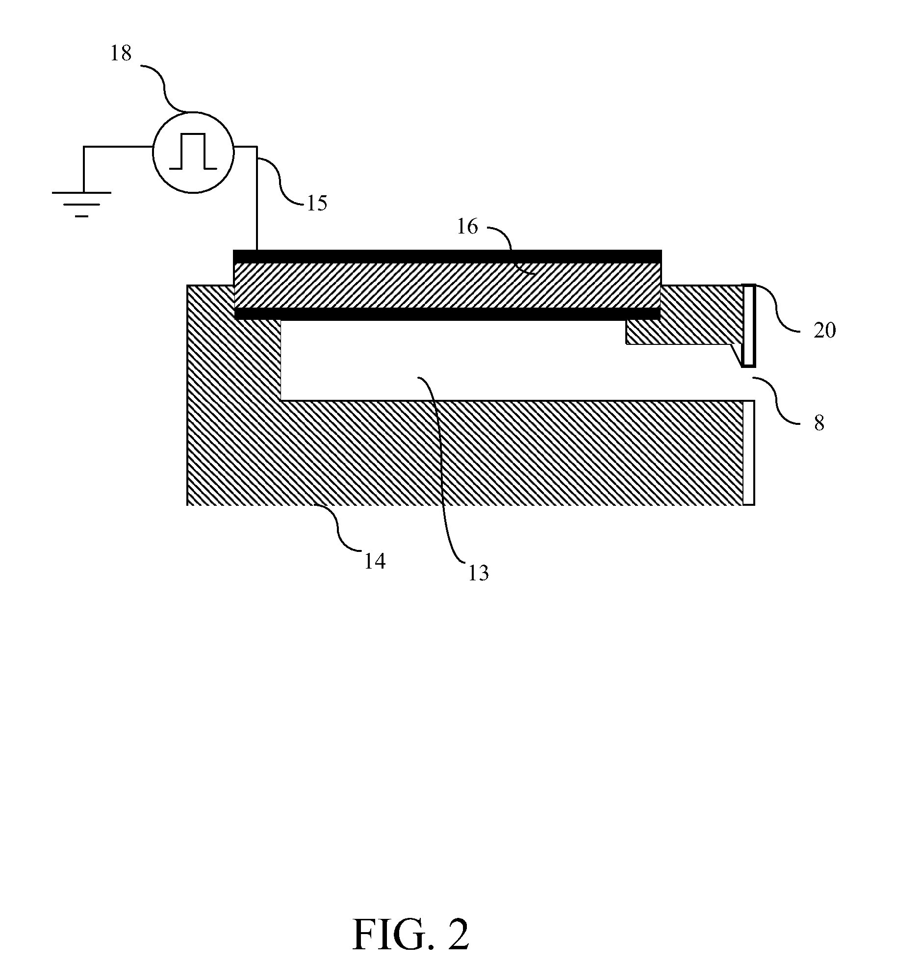
[0008]An object of the present invention is to reduce the power dissipation during charging and discharging of a piezoelectric element in the print head. According to the present invention, this object is achieved by an inkjet printing apparatus, comprising a print head, the print head comprising an ink duct, a piezoelectric element operatively coupled to the ink duct, and a control device configured to control an ink drop ejection from the ink duct by actuation of the piezoelectric element. The control device comprises a current source, a number of power supplies, and a switch, connected between the current source and the number of power supplies, wherein the current source is configured to generate a current for actuating the piezoelectric element by charging and discharging, and the switch is configured to connect the current source and one of the number of power supplies, the one of the number of power supplies being selected such that a lowest voltage difference over the current source exists.
[0020]Each piezoelectric element may have its own control device and may operate independently of other control devices, giving this approach a large flexibility. Deviations and ripple at the voltage input terminals do not disturb the functioning, because the control device uses the voltage drop across the current source as switching criterion. A voltage ladder may be constructed by selecting a plurality of adequate voltage levels. The voltage ladder may be constructed only once per piezoelectric element.
[0024]In an embodiment, an inkjet printing apparatus may comprise a number of piezoelectric elements and a number of current sources. The number of power supplies and the number of current sources may be operatively connected by means of a multiplexer. The multiplexer may comprise a number of input terminals and a number of output terminals. Each power supply may be connected to a respective input terminal and each current source may be connected between a respective output terminal and a respective one of the number of piezoelectric elements. In this manner, only one switching device, the multiplexer, is embodied and this may be advantageous in the case that each piezoelectric element needs to be charged according to an approximately same voltage ladder by switching for each step on the voltage ladder to a next higher voltage level by connecting to a corresponding input terminal of the multiplexer. For discharging the same advantage may be achieved.

Problems solved by technology

In an inkjet printer with, for example, 128 nozzles per print head such power dissipation results in a substantial loss of energy.
When using a higher jet frequency or a larger number of nozzles per print head the energy loss becomes even larger.
However, the dissipated power is still large since the power supply voltage is constantly present over the plurality of capacitors causing power dissipation during charging and discharging of the piezoelectric element of each equal to the amount of ½ CAVA2.

Method used


Image

  • Driver circuit for driving a print head of an inkjet printer
  • Driver circuit for driving a print head of an inkjet printer
  • Driver circuit for driving a print head of an inkjet printer

Examples


first embodiment

[0057]In FIG. 3, only one piezoelectric element 37 is shown. In practice, an inkjet printing apparatus may comprise a plurality of piezoelectric elements and a plurality of current sources for driving a plurality of nozzles independently. A first embodiment is shown in FIG. 5a. A number of power supplies 311, 321, 331, 341, each delivering a voltage of x V, may be connected in series to switch 351 having five input terminals 351a, 351b, 351c, 351d, 351e, outputting voltage levels 0 V, x V, 2x V, 3x V and 4x V, respectively. An output terminal of the switch 351 may be connected to a number of current sources 361a, 361n, of which a first current source 361a and a second current source 361n are shown in FIG. 5a. The current sources 361a, 361n may charge and discharge piezoelectric elements 371a, 371n, respectively, such as described above with respect to FIG. 3. A first piezoelectric element 371a and a second piezoelectric element 371n are shown in FIG. 5a. The charging of the piezoele...

second embodiment

[0058]In FIG. 5a, one switch 351 is shown. a control circuit for use with a plurality of piezoelectric elements is shown in FIG. 5b in which at least two switch 352a, 352n are arranged in the control circuit. A number of power supplies 312, 322, 332, 342, each delivering a voltage of x V, may be connected in series to the at least two switches 352a, 352n. A first switch 352a and a second switch 352n are shown in FIG. 5b. The first switch 352a is configured with five input terminals 352b, 352c, 352d, 352e, 352f, outputting voltage levels 0 V, x V, 2x V, 3x V and 4x V, respectively. The second switch 352n is configured with five input terminals 352v, 352w, 352x, 352y, 352z, outputting voltage levels 0 V, x V, 2x V, 3x V and 4x V, respectively. The first switch 352a is connected to a first current source 362a. The second switch 352n is connected to a second current source 362n. The first current source 362a may charge and discharge a first piezoelectric element 372a. The second current...


PUM


Abstract

An inkjet printing apparatus includes a print head having an ink duct, a piezoelectric element operatively coupled to the ink duct, and a control device for controlling an ink drop ejection from the ink duct by actuation of the piezoelectric element. The control device includes a current source, a number of power supplies, and a switch, connected between the current source and the number of power supplies. The current source is configured to generate a current for actuating the piezoelectric element by charging and discharging. The switch is configured to connect the current source and one of the number of power supplies. The one of the number of power supplies is selected such that a lowest voltage difference over the current source exists.

Description

CROSS-REFERENCE TO RELATED APPLICATIONS[0001]This application is a Continuation of copending PCT International Application No. PCT / EP2009 / 063894 filed on Oct. 22, 2009, which designated the United States, and on which priority is claimed under 35 U.S.C. §120. This application also claims priority under 35 U.S.C. §119(a) on Patent Application No. 08168333.6, filed in Europe on Nov. 5, 2008. The entire contents of each of the above documents is hereby incorporated by reference into the present application.BACKGROUND OF THE INVENTION[0002]1. Field of the Invention[0003]The present invention relates to an inkjet printing apparatus, comprising a print head, the print head comprising an ink duct, a piezoelectric element operatively coupled to the ink duct, and a control device configured to control ink drop ejection from the ink duct by actuation of the piezoelectric element.[0004]2. Description of Background Art[0005]Inkjet printers comprising piezoelectric elements are well known in the...

Claims


Application Information

Patent Timeline
IPC IPC(8): B41J29/38
CPCB41J2/0452B41J2/04581B41J2/04541
Inventor SIMONS, JOHANNES M.M.SCHRIJVER, ERWIN
Owner OCE TECH
Learn More