
Workpiece carrier

a workpiece and carrier technology, applied in the direction of vices, chucks, printing, etc., can solve the problems of long interruption of processing, onerous and time-consuming releasing and fixing of workpieces, and achieve the effect of fast and easy loading and unloading, fixing and releasing workpieces, and being easy and quick to move and unload

Inactive Publication Date: 2011-10-27
OERLIKON SURFACE SOLUTIONS AG PFAFFIKON
View PDF3 Cites 3 Cited by
  • Summary
  • Abstract
  • Description
  • Claims
  • Application Information

AI Technical Summary

Benefits of technology

[0004]It is the object of the invention to provide a workpiece carrier of the generic type which can accommodate workpieces with varying shaft diameters and nevertheless allows for fast and easy loading and unloading. This object is achieved by the features in the characterizing portion of claim 1.

Problems solved by technology

Whenever the diameters of the workpiece shafts change the workpiece carrier must be exchanged which causes a lengthy interruption of the processing.
However, the releasing and fixing of workpieces is rather onerous and time-consuming.

Method used


Image

  • Workpiece carrier
  • Workpiece carrier

Examples


Embodiment Construction

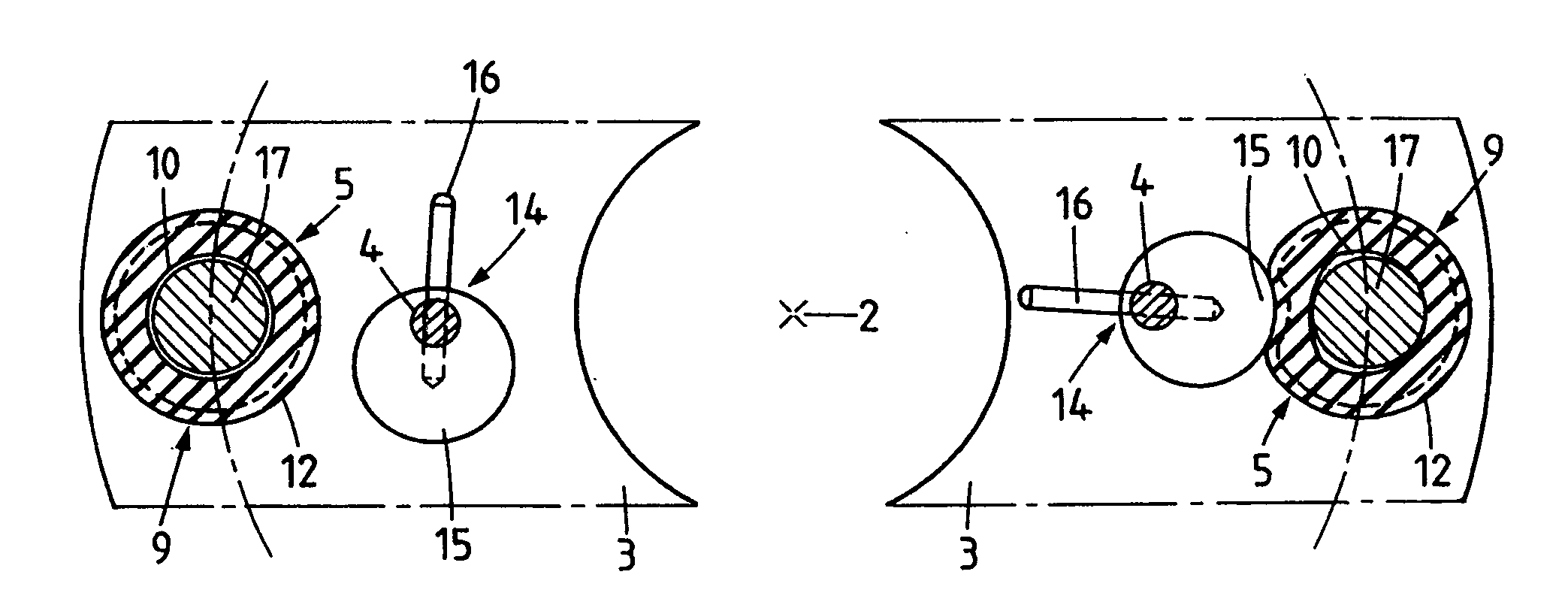
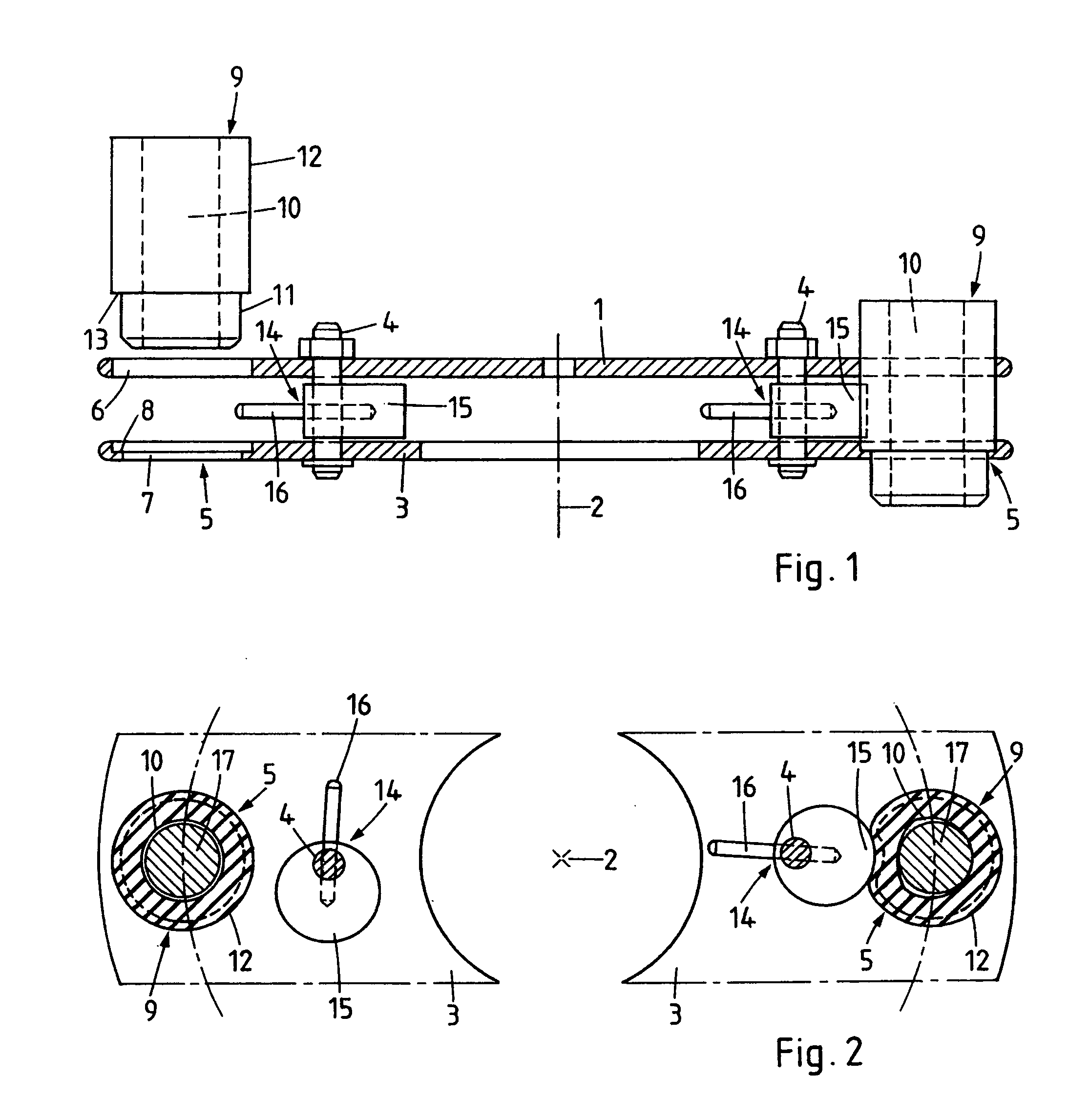
[0009]The workpiece carrier comprises a base which consists of a disk-shaped upper part 1 (not shown in FIG. 2) which is mounted so as to be rotatable about a vertical axis 2 and a ring-shaped lower part 3 which is arranged below the upper part 1 at a distance and connected to the same by a plurality of vertical bolts 4 each penetrating the upper part 1 and in the lower part 3. Along the circumference of the base workpiece holders are arranged, each with a recess for taking up one of the workpieces. The recesses 5 are distributed uniformly about the circumference of the base at a fixed distance from the axis 2. Each recess 5 consists of a round hole 6 in the upper part 1 and a coaxial round hole 7 of slightly smaller diameter in the lower part 3. The hole 7 is surrounded by a rim 8 which is slightly recessed from the upper surface of the lower part 3. The outer diameter of the rim 8 is equal to the diameter of the hole 6 in the upper part 1.

[0010]Each of the recesses 5 accommodates ...


PUM


Abstract

A workpiece carrier comprises a base with an upper part rotatable about a vertical axis and a lower part connected to the upper part at a distance by bolts. Workpiece holders each comprise a sleeve of elastically deformable material like rubber surrounding a duct where the shaft of a workpiece can be inserted, the sleeve being accommodated in a recess on the base. The vertical position of the sleeve which extends through holes in the upper part and lower part of the base, respectively, is fixed by a stop formed between a recessed rim surrounding the hole in the lower part and a downward-facing projecting rim of the sleeve. The shaft can be fixed by swivelling a lever about one of the bolts into an active position where a compressing surface of the same compresses the sleeve such that the shaft is jammed and released by swivelling the lever back into an inactive position where the compressing surface is not in contact with the sleeve.

Description

FIELD OF THE INVENTION[0001]The invention concerns a workpiece carrier as used in various processing installations where workpieces with a shaft like, for instance, milling tools, are processed, e.g., by slide grinding or other surface treatment methods.PRIOR ART[0002]Workpiece carriers of the generic type are known where each workpiece holder is in the shape of a sleeve consisting of a rigid material like steel which accommodates the shaft of the workpiece. To keep the latter reliably in place the sleeve must narrowly surround the shaft, i.e., the inside diameter of the sleeves must conform to the diameter of the shafts. Whenever the diameters of the workpiece shafts change the workpiece carrier must be exchanged which causes a lengthy interruption of the processing.[0003]It is also known to use a threaded bolt engaging with a radial threaded bore in the sleeve which can fix a shaft whose diameter is smaller than the inside diameter of the sleeve by clamping it against the opposite...

Claims


Application Information

Patent Timeline
IPC IPC(8): B25B1/00B24B41/06
CPCB23B31/1175B24B41/067B24B41/06
Inventor WILFRED, THOM
Owner OERLIKON SURFACE SOLUTIONS AG PFAFFIKON
Learn More