
Ammonia burning internal combustion engine

Inactive Publication Date: 2011-10-27
TOYOTA JIDOSHA KK
View PDF10 Cites 61 Cited by
  • Summary
  • Abstract
  • Description
  • Claims
  • Application Information

AI Technical Summary

Benefits of technology

[0050]Summarizing the advantageous effects of the invention, according to the present invention, it is possible to suppress a drop in combustibility of a highly combustible substance due to ammonia.
of the invention, according to the present invention, it is possible to suppress a drop in combustibility of a highly combustible substance due to ammonia.

Problems solved by technology

However, ammonia is harder to burn compared with fossil fuels.
However, if the air-fuel mixture fed into the combustion chamber contains ammonia, ammonia causes the combustibility of the highly combustible substance to drop.
However, Japanese Patent Publication (A) No. 5-332152 does not consider this at all.

Method used


Image

  • Ammonia burning internal combustion engine
  • Ammonia burning internal combustion engine
  • Ammonia burning internal combustion engine

Examples


first embodiment

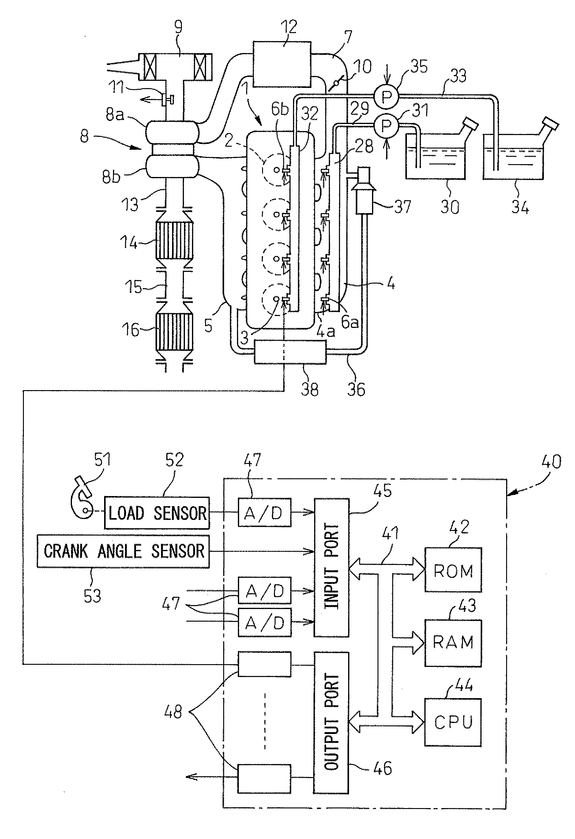
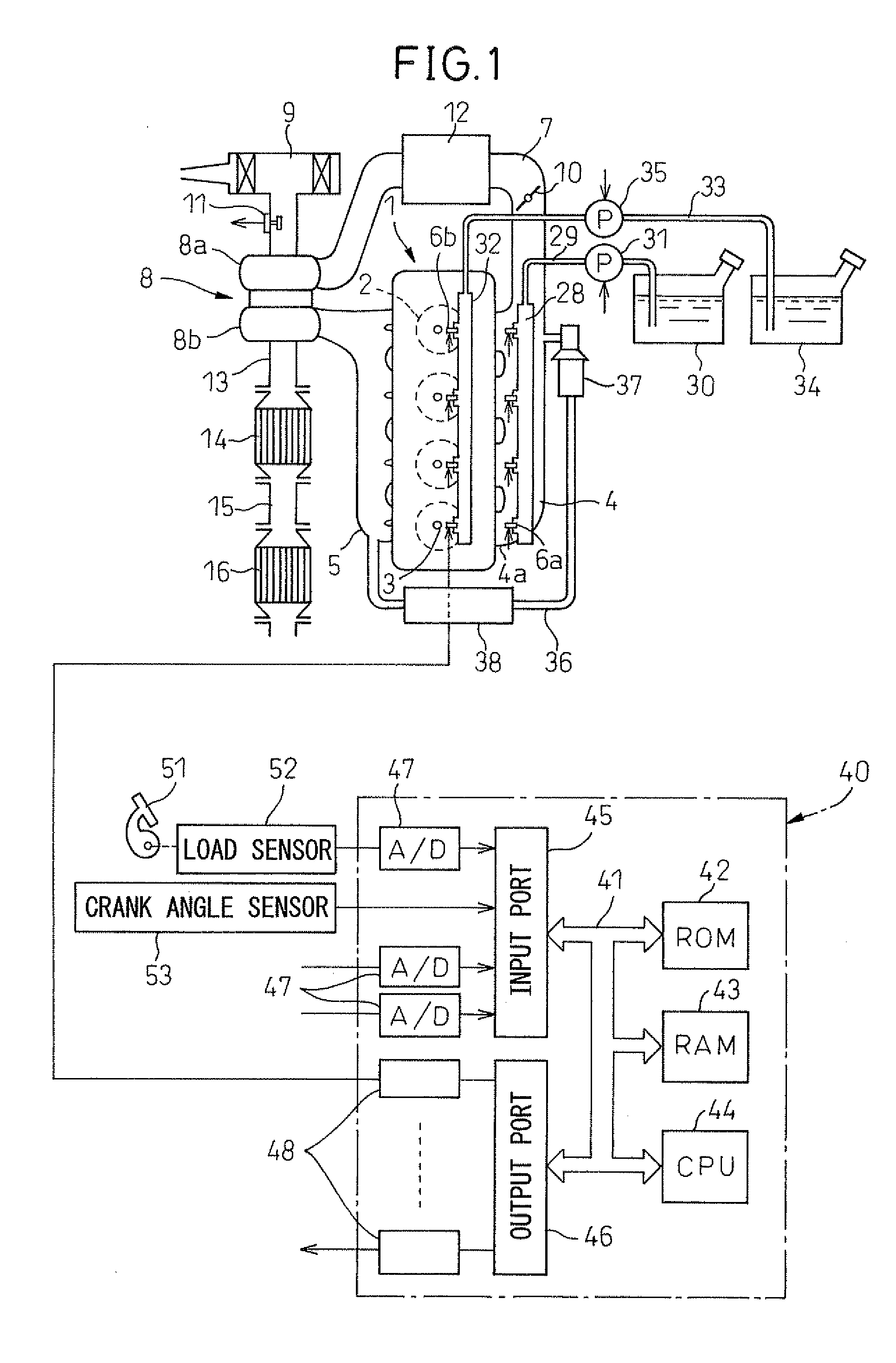
[0119]First, the first aspect will be explained. In general, the higher the temperature of the air-fuel mixture in the combustion chamber 2 when the piston is located near the compression top dead center (hereinafter, referred to as the “compression end temperature”), the easier the combustion of the air-fuel mixture in the combustion chamber 5 becomes. Further, one method for making the compression end temperature rise, is to make the temperature of the intake gas fed into the combustion chamber 2 rise. Therefore, in the present embodiment, when the amount of ammonia fed into the combustion chamber 2 increases, the temperature of the intake gas fed into the combustion chamber 2 is made to rise.

[0120]FIG. 5 shows the relationship between the amount of ammonia fed into the combustion chamber 2 and the temperature of the intake gas fed into the combustion chamber 2. As shown in FIG. 5, in the present embodiment, as the amount of ammonia fed into the combustion chamber 2 increases, the...

second embodiment

[0131]Further, in the ammonia burning internal combustion engine of the second embodiment, the closing timing of the intake valve 24 can be changed by the variable valve timing mechanism. By changing the closing timing of this intake valve 24, the de facto compression ratio can be changed. That is, when the closing timing of the intake valve 24 is near the intake bottom dead center, the ratio of the volume of the combustion chamber when the piston is located at the compression top dead center with respect to the volume of the combustion chamber at the time of closing of the intake valve 24 is large. Conversely, when the closing timing of the intake valve 24 is a timing other than the intake bottom dead center, the ratio of the volume of the combustion chamber when the piston is located at the compression top dead center with respect to the volume of the combustion chamber at the time of closing of the intake valve 24 is small.

[0132]Here, if the ratio of the volume of the combustion ...

third embodiment

[0135]Next, the first aspect will be explained. As explained above, the higher the compression end temperature, the easier the air-fuel mixture in the combustion chamber 5 becomes to burn. One method of making such compression end temperature rise is to increase the amount of the intake gas (hereinafter, referred to as the “amount of filled intake gas”) filled in the combustion chamber 2 at the time of closing of the intake valve 24. Therefore, in the present aspect, when the amount of ammonia fed into the combustion chamber 2 increases or when the ratio of the amount of the ammonia to the total feed amount of the ammonia and highly combustible substance into the combustion chamber 2 increases, the amount of filled intake gas is made larger.

[0136]FIG. 10 shows the relationship between the amount of ammonia fed into the combustion chamber 2 and the amount of filled intake gas. As shown in FIG. 10, in the present embodiment, the larger the amount of ammonia fed into the combustion cha...


PUM


Abstract

An ammonia burning internal combustion engine can feed ammonia and a highly combustible substance burning easier than ammonia to a combustion chamber. When the amount of ammonia fed into the combustion chamber is increased or when the ratio of the amount of the ammonia to the total amount of the ammonia and the highly combustible substance fed into the combustion chamber is increased, the operating parameters of the internal combustion engine are controlled so the air-fuel mixture fed into the combustion chamber is made easier to burn. As a result, an ammonia burning internal combustion engine designed to suppress a drop in combustibility of auxiliary fuel due to ammonia, can be provided.

Description

BACKGROUND OF THE INVENTION[0001]1. Field of the Invention[0002]The present invention relates to an ammonia burning internal combustion engine.[0003]2. Description of the Related Art[0004]In an internal combustion engine, in the past, the fuel used has mainly been fossil fuels. However, in this case, burning such fuels produces CO2, which causes global warming. On the other hand, burning ammonia does not produce CO2 at all. Thus, there is known an internal combustion engine made so as to use ammonia as fuel and not produce CO2 (for example, see the following prior art).[0005]As prior art, there is Japanese Patent Publication (A) No. 5-332152.SUMMARY OF THE INVENTION[0006]However, ammonia is harder to burn compared with fossil fuels. Therefore, when using ammonia as fuel, some sort of measure is required for making the ammonia easier to burn. Thus, in the above-mentioned internal combustion engine, exhaust heat is utilized to reform the ammonia so as to produce reformed gas comprised...

Claims


Application Information

Patent Timeline
IPC IPC(8): F02B43/10F02D41/02
CPCF02M25/0707F02M25/14F02M37/0088Y02T10/121Y02T10/36F02M21/0287Y02T10/32F02D19/0644F02D19/0665F02D19/0689F02D19/0692F02D19/081F02M25/0727F02D15/00F02D19/105F02D35/026F02D41/0002F02D41/0007F02D41/0025F02D41/0047F02D41/005F02D41/401F02D2041/001F02D2041/1468F02D2200/0414F02D2250/31F02D2700/03F02M26/05F02M26/23Y02T10/30Y02T10/40Y02T10/12
Inventor MICHIKAWAUCHI, RYOITO, YASUSHIIWATANI, KAZUKITANNO, SHIRO
Owner TOYOTA JIDOSHA KK
Learn More