
Method and apparatus for crest factor reduction in telecommunications systems

a technology of crest factor and telecommunications system, applied in the field of telecommunications system, can solve the problems of high power consumption, significant increase of out-of-band emissions, and low power efficiency

Inactive Publication Date: 2011-10-20
QUALCOMM INC
View PDF4 Cites 32 Cited by
  • Summary
  • Abstract
  • Description
  • Claims
  • Application Information

AI Technical Summary

Benefits of technology

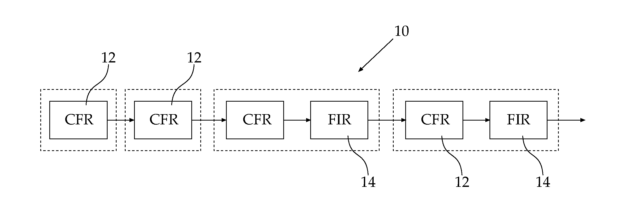
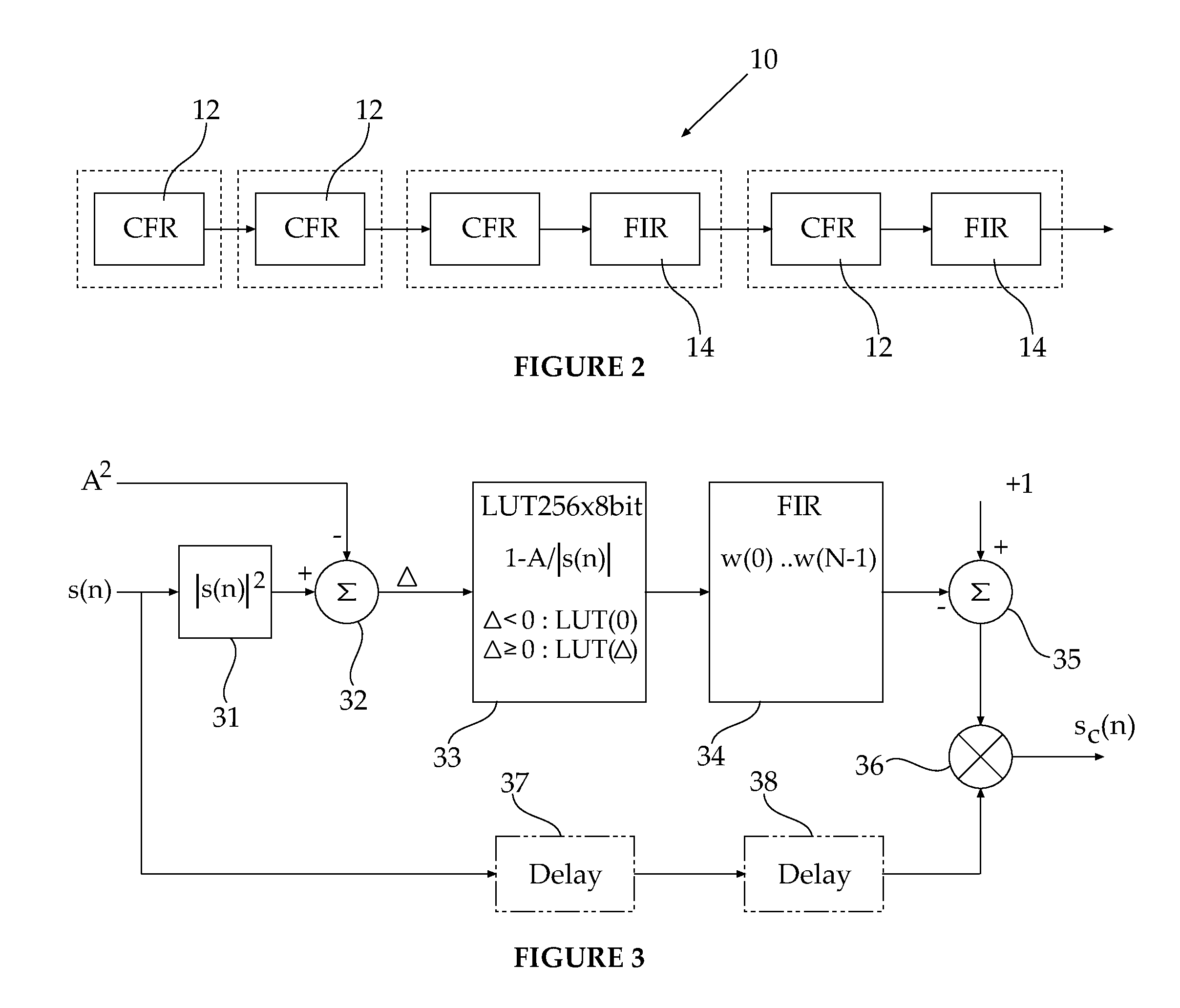
[0008]The current invention provides a solution to the above drawback by chaining two or more original digital filter, preferably Finite Impulse Response (FIR)-only based peak-windowing blocks, with no feedback. This enables a simpler, fully pipelined design (which basically cascades identical simple hardware blocks). Using this multistage approach allows for gradual clipping of the signal, by taking care of the higher peaks first, in the early stages along the signal flow, and then of lower peaks on the later stages.
[0011]There is provided, according to the present invention, a method for reducing Peak-to-Average Power Ratio (PAPR) of a transmitted signal in a wireless telecommunication system utilizing Crest Factor Reduction (CFR) technique, the method including performing peak-windowed clipping of a transmitted signal using at least two cascaded clipping stages; individually configuring parameters for each clipping stage before said step of performing; and filtering the clipped signal to suppress unwanted out-of-band emissions after at least one clipping stage.

Problems solved by technology

High linearity requirements lead to low power efficiency and, therefore, to high power consumption in the PA.
The simplest way to reduce the PAPR is to literally clip the signal, but this significantly increases the out-of-band emissions.
Although (1) preserves the signal phase, abrupt amplitude changes appear in the clipped signal, causing significant out-of-band spectrum re-growth.
In practice, however, the peaks may often appear rather frequently in the signal time envelope; this leads to overlapping of windows surrounding closely located peaks and, therefore, to excessive clipping of the signal and, thus, to its unreasonable distortion.
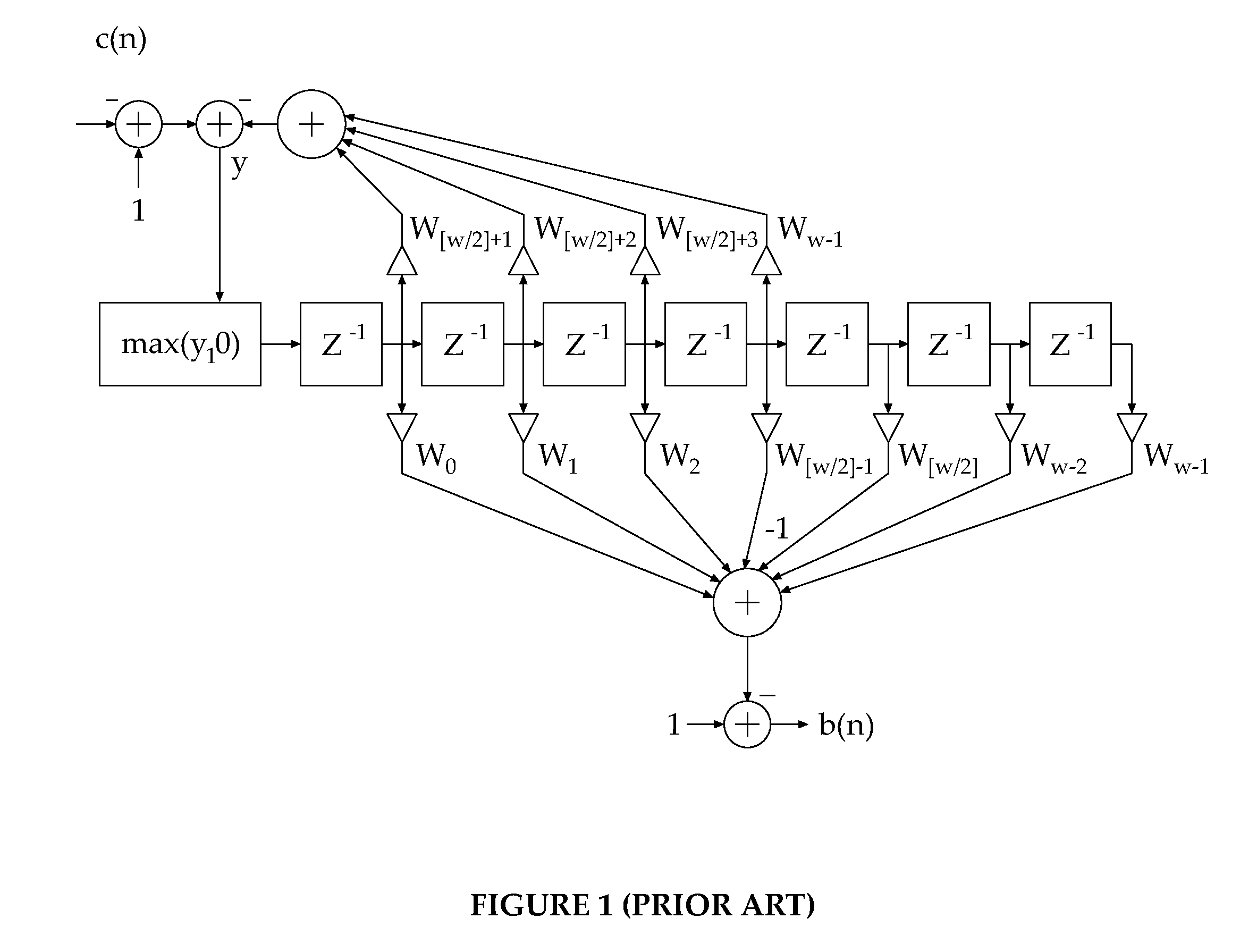
While providing the desired improvement, the feedback portion breaks the simple structure of the FIR filter, which is well exploited in the industry, and generally is less suitable for a pipelined design supporting high sampling rates of the data.

Method used


Image

  • Method and apparatus for crest factor reduction in telecommunications systems
  • Method and apparatus for crest factor reduction in telecommunications systems
  • Method and apparatus for crest factor reduction in telecommunications systems

Examples


Embodiment Construction

[0018]The present invention relates to a method and system for wireless telecommunications providing improved performance of the CFR technique. This is accomplished by applying multi-stage, gradual peak-windowed clipping of the transmitted signal followed by its filtering for out-of-band spectrum shaping. The current invention answers the drawbacks of the prior art by chaining two or more original digital filter-only based, peak-windowing blocks (with no feedback). Using this multistage approach, the the signal can be clipped gradually, by clipping the higher peaks first, in the early stages along the signal flow, and then the lower peaks on the later ones. In this way, the peaks are gradually ‘diluted’ in time, each stage sees fewer events of close peaks and, thus, window overlapping is avoided to a high degree, thus eliminating the need for a protective feedback circuit. An additional advantage of the multistage approach is its programmable flexibility: different signal schemes an...


PUM


Abstract

A method and device for reducing Peak-to-Average Power Ratio (PAPR) of a transmitted signal in a wireless telecommunication system utilizing CFR technique, the method including performing peak-windowed clipping of a transmitted signal using at least two cascaded clipping stages and individually configuring parameters for each clipping stage before performing the peak-windowed clipping.

Description

FIELD OF THE INVENTION[0001]The present invention relates to telecommunications systems, in general and, in particular, to a transmitter implementing the Crest-Factor Reduction (CFR) technique.BACKGROUND OF THE INVENTION[0002]In modern communications systems using CDMA or OFDM modulation schemes, the signal is not a constant envelope signal, which means higher linearity requirements for the power amplifier (PA). In a wideband code division multiple access (WCDMA) system, the downlink signal is a sum of signals intended for different users. If the independent constituent carriers are combined in a multicarrier system in the digital domain, the Peak-to-Average Power Ratio (PAPR) grows even further. OFDM systems are multicarrier by definition, therefore leading to high PAPR as well. In all the above cases, the composite signal is Gaussian distributed that leads to a high peak-to-average-power-ratio (PAPR). High linearity requirements lead to low power efficiency and, therefore, to high...

Claims


Application Information

Patent Timeline
IPC IPC(8): H04B15/00
CPCH04L27/2624
Inventor GOTMAN, MAXIMOVED, TALMATSRAFI, ORENTOUBOUL, ASSAF
Owner QUALCOMM INC
Learn More