
Hardening of flexible trailing arms

a technology of flexible trailing arms and hardening, which is applied in the manufacture of tools, heat treatment equipment, furnaces, etc., can solve the problems of high cost, high cost, and high brittleness of martensite after quenching, so as to save time and energy and high quality

Inactive Publication Date: 2011-10-20
WEWELER NEDERLAND BV
View PDF7 Cites 9 Cited by
  • Summary
  • Abstract
  • Description
  • Claims
  • Application Information

AI Technical Summary

Benefits of technology

[0010]By this method is obtained a trailing arm with a substantially bainitic structure, at least at the outside regions. A bainitic structure is more ductile than the martensite structure which is common in flexible trailing arms, whereby a tempering step, which is necessary with a martensite structure, can be omitted, which saves energy use and time.
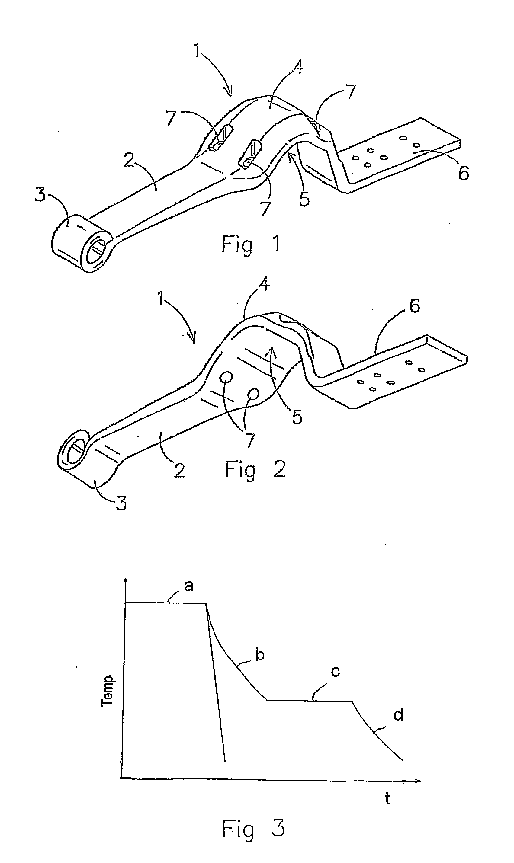
[0014]The method according to the invention can be used with particular advantage when the flexible trailing arm is shaped by means of forging. The trailing arm is then advantageously formed in one forging step, whereby no transport and reheating between forming steps is necessary. Furthermore the forged arm can with particular advantage be submerged directly in the liquid salt after it is ejected or otherwise removed from the forging device. In this manner the formed flexible trailing arm does not have to be reheated to an austenite structure to harden it. The trailing arm is simply formed in one step and then directly out of the forging device austempered in the liquid salt. The resulting trailing arm has a bainitic structure and has a sufficient tensile strength of preferably 1300-1600 N / mm. This specifically advantageous manufacturing method thus provides high quality flexible trailing arms in an efficient way and cost effective way, in which in particular time and energy is saved.

Problems solved by technology

The quenching in oil is hazardous in view of fire risks.
Furthermore the oil is a danger for the environment.
The resulting martensite structure after quenching is very hard and brittle, which is undesired for the flexible trailing arm, which in use is subjected to dynamic loads.

Method used


Image

  • Hardening of flexible trailing arms
  • Hardening of flexible trailing arms
  • Hardening of flexible trailing arms

Examples


Embodiment Construction

[0023]In FIG. 1 is shown an exemplary embodiment of a flexible trailing arm 1 for a wheel axle suspension. The shown trailing arm 1 is made from steel and comprises a spring portion 2, a hinge eyelet 3 on the front end of the spring portion 2, a curved portion 4 is formed, which curved portion 4 has a concave contact surface 5 which is directed downward in the example shown. Following on from the curved portion 4, an end portion 6 is formed which is intended for fitting a pneumatic spring thereto.

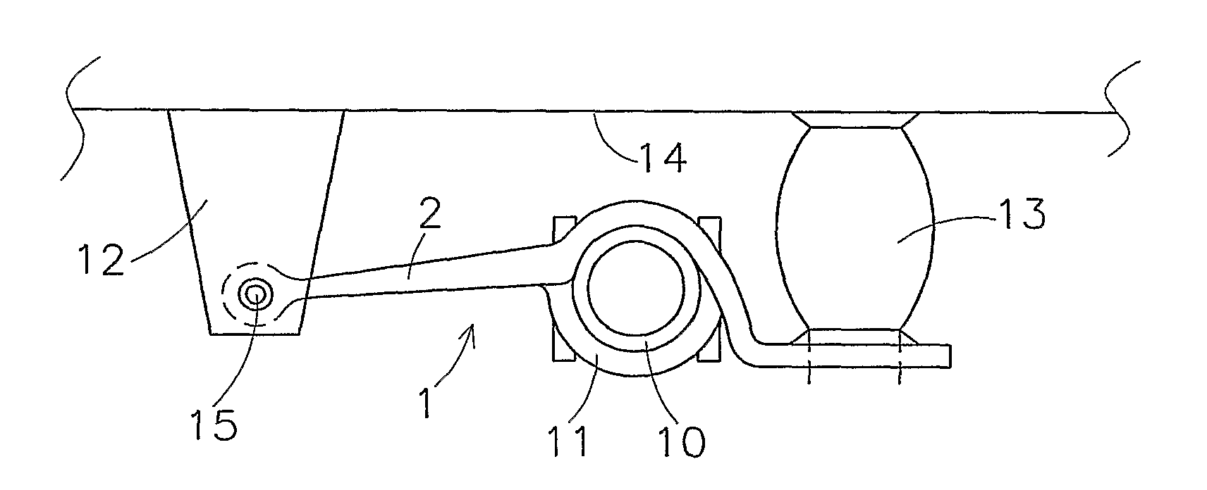
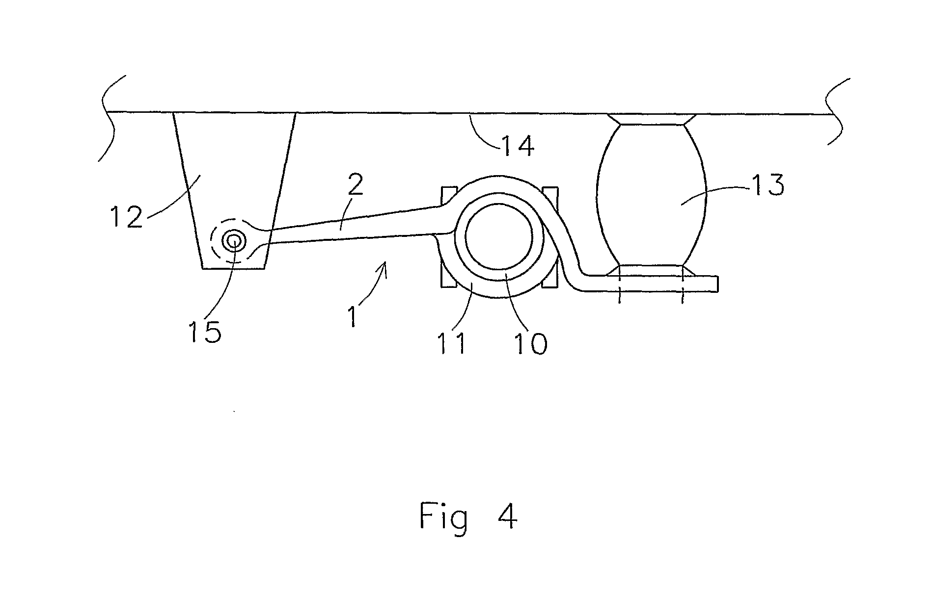
[0024]In FIG. 4 is shown an exemplary wheel axle suspension of for example a trailer or a lorry. On each side of the vehicle, the suspension comprises has a trailing arm 1 which extends substantially in the longitudinal direction of the vehicle. The axle body 10 of the wheel axle is attached to the trailing arm 1 at the mounting portion of the trailing arm 1 by means of a clamping member 11. Each trailing arm 1 is hingedly connected to a bearing bracket 12, which is arranged on the vehicle ...


PUM

PropertyMeasurementUnit
temperatureaaaaaaaaaa
flexibleaaaaaaaaaa

Abstract

The invention relates to a method for manufacturing of a flexible trailing arm for a wheel axle suspension of a vehicle such as a lorry or a trailer. In the method a steel blank is heated. Next, the blank is formed into the desired shape of the trailing arm by means of a suitable forming process. Following that the trailing arm is austempered by cooling it in a warm fluid medium.

Description

CROSS-REFERENCE TO RELATED APPLICATIONS[0001]This application is the National Stage of International Application No. PCT / NL2009 / 000226, filed Nov. 19, 2009, which claims the benefit of Netherlands Application No. NL 2002248, filed Nov. 24, 2008, the contents of which is incorporated by reference herein.FIELD OF THE INVENTION[0002]The present invention relates to the manufacturing of flexible suspension arms for a wheel axle suspension of a vehicle, such as a lorry or a trailer. Such suspension arms are referred to in the art as flexible trailing arms or spring arms.BACKGROUND OF THE INVENTION[0003]A wheel axle suspension of a trailer or a lorry has a trailing arm on each side of the vehicle which extends substantially in the longitudinal direction of the vehicle. The axle body of the wheel axle is attached to the trailing arms. Each trailing arm is hingedly connected at the front, viewed in the direction of travel of the vehicle, to a bearing bracket which is arranged on the vehicle...

Claims


Application Information

Patent Timeline
Patent Type & Authority Applications(United States)
IPC IPC(8): B60G3/12C21D8/00
CPCB60G7/001B60G2200/31B60G2202/112B60G2202/152C21D2211/002B60G2206/8402C21D1/20C21D1/46C21D9/0068B60G2206/81022
Inventor AALDERINK, DERK GEERTVERHOOFSTAD, MARTINUS JOZEF MARIA
Owner WEWELER NEDERLAND BV
Learn More