
Hollow shaft connection device

a technology of connection device and hollow shaft, which is applied in the direction of coupling, roof, transportation and packaging, etc., can solve the problems of high spring rate of the chassis spring in heavy-duty trucks, high stress on conventional connection device, so as to improve the progression of characteristic force lines, save weight, and cost-effective

Active Publication Date: 2011-10-20
ZF FRIEDRICHSHAFEN AG
View PDF9 Cites 18 Cited by
  • Summary
  • Abstract
  • Description
  • Claims
  • Application Information

AI Technical Summary

Benefits of technology

[0016]Proceeding from this background, the problem addressed by the present invention is to create a connection device for a torque transmitting connection between hollow shafts and their connection components which overcomes the named disadvantages. The connection device should make it possible to transmit high torques without damage between especially thin-walled hollow shafts and the respective connection components, while simultaneously guaranteeing a high degree of safety against failure. In addition, it should be possible to produce and assemble the connection between the hollow shaft and the connection component cost-effectively and reliably, and using the connection device, it should be possible to implement further constructive objectives, in particular bearing functions, in a simple manner.

Problems solved by technology

Because the spring rates of the chassis springs in heavy-duty trucks are inevitably high, due to the heavy vehicle loads, unevennesses in the road surface or even vibrations and structure-borne noise, resulting from axles and the drive train, are still transmitted, to a considerable extent, to the chassis via the axle spring mounting.
Such suspension devices for driver's cabins have a complex design, particularly with increased requirements on supporting transverse forces or kinematics, for example the suppression of pitching and rolling and sideways control.
Conventional connection devices, particularly between roll stabilizers and torque levers assigned to them, are exposed to very high stresses during their service life.
In both cases, however, a connection produced in this manner, between the torque lever and the torsion tube, represents a highly stressed potential weak point.
Pure press connections, between the torsion tubes and torque levers, can be established by comparatively gentle cold forming; however, they often fail to attain the necessary service life in the case of the strong forces and high torques that occur.
For this reason, interference fits, for example, between the hollow shaft and the connection component cannot be implemented with the fixed press fit necessary for transmitting high torques.
When the comparatively weak specific forces that can be transmitted are exceeded, the tube wall will therefore separate in the area of the press fit of the torque lever, or the tube wall can be pressed in, which leads to the subsequent failure of the tube cross section.
Despite this proposed improvement, the possibility disclosed in this publication for connecting hollow shafts to connection components is limited to specific intended uses, or requires possibly a series of additional component assemblies or parts for implementing further functions, such as are necessary, particularly however not exclusively, in the case of roll stabilizers for driver's cabs.
For roll stabilization of vehicles axles, anti-roll stabilizers, consisting mainly of solid material and bent from one-piece, are used in the prior art, which have a corresponding high mass, especially in heavy utility vehicles, and whose degree of material utilization is extremely unfavorable with respect to the intended twisting and torsional rigidity.
The replacement of the massive anti-roll stabilizers by bulky, comparatively thin-walled and thus lighter weight hollow shafts has to date often been unsuccessful because of the problematic connection techniques between such hollow shafts and the torque transmitting connection components, such as torque levers.

Method used


Image

  • Hollow shaft connection device
  • Hollow shaft connection device
  • Hollow shaft connection device

Examples


Embodiment Construction

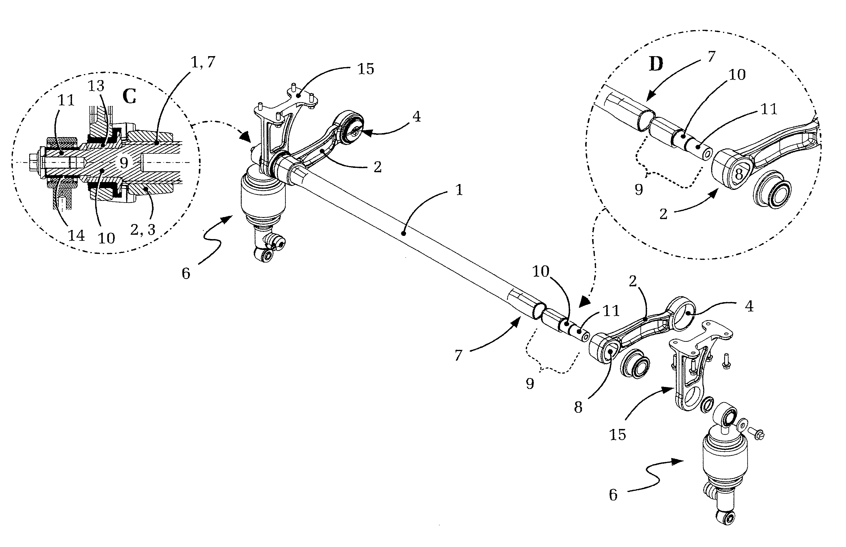
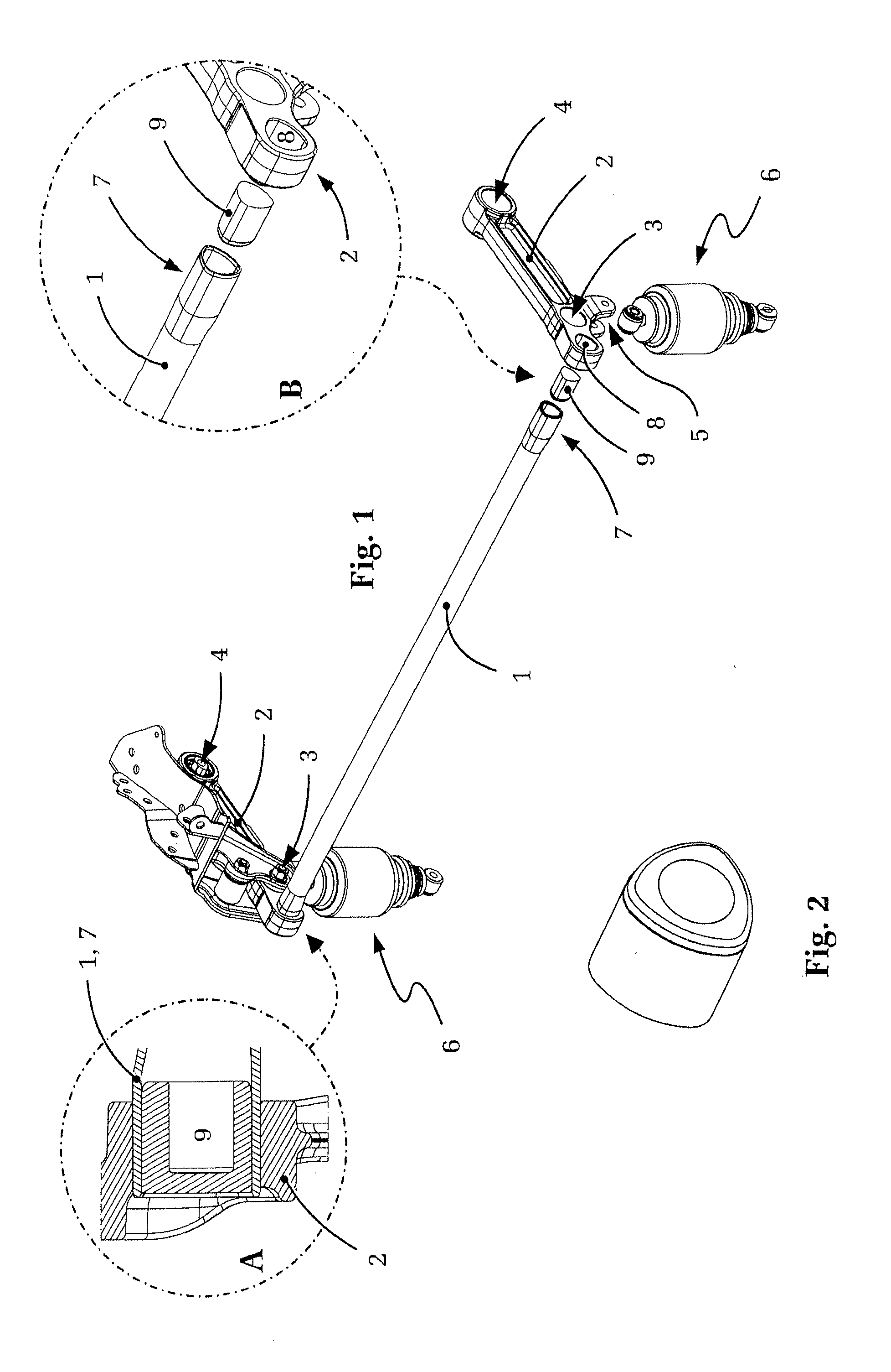
[0054]FIG. 1 shows a roll stabilizer for a driver's cabin, according the prior art, wherein the represented roll stabilizer has a press-fit plug connection device on each of the two ends. First, the hollow shaft 1 can be seen acting as a torsion element having a torque lever 2 disposed on both ends. To begin with, each of the two torque levers 2 supports two bearing points 3 and 4 provided with elastomer bearings, wherein the bearing point 3 near the shaft serves, in each case, for connecting the roll stabilizer to a driver's cab (not shown) and the bearing point 4, away from the shaft, serves for connecting to the vehicle chassis (also not shown). The function of the bearing point pairs 3, 4 of each of the two torque levers 2—while maintaining the functionality of the roll stabilizer—however, also can be switched, which means that the bearing points 3 near the shaft are hinged to the chassis, and the bearing points 4 spaced from the shaft, in contrast, is hinged to the driver's cab...


PUM


Abstract

A connection device for the torque transmitting connection of a connection component (2) to a hollow shaft (1). The connection component (2) comprises a penetrating recess (8) corresponding in shape to the outside cross section of the hollow shaft (1) for receiving one end of the hollow shaft (1), and the hollow shaft comprises a press-fit plug (9) in the area of the connection to the connection component (2) that forms an interference fit with the inner cross section of the hollow shaft (1). Preferably, the connection device is a press-fit plug (9) additionally designed as a bearing seat (10, 11) for at least one bearing (13, 14) assigned to the hollow shaft. The connection device allows durable and reliable transmission of high torques and it is possible to connect further components to the connection between the hollow shaft and the connection component. The connection device allows a reduction in construction space, mass and costs.

Description

[0001]This application is a National Stage completion of PCT / DE2009 / 050053 filed Oct. 1, 2009, which claims priority from German patent application serial no. 10 2008 049 940.4 filed Oct. 2, 2008.FIELD OF THE INVENTION[0002]The invention relates to a connection device for the torque transmitting coupling of a hollow shaft to a connection component.BACKGROUND OF THE INVENTION[0003]Connection devices, of the initially named type, are used for the connection of all types of torque transmitting components to associated shafts or hollow shafts. Conventional connections of this type are used, for example—but by no means exclusively—in the assembly of torque levers or control arms on torsion rods or stabilizer devices. One field of use, merely by way of example, is the area of shock and vibration absorbing suspension of motor vehicle driver's cabins, especially for trucks and similar heavy-duty trucks, in order to uncouple the driver's cabin with respect to vibrations and motions of the ve...

Claims


Application Information

Patent Timeline
Patent Type & Authority Applications(United States)
IPC IPC(8): F16D1/02B60G21/055B62D33/063
CPCB60G21/052B60G2204/1226B60G2204/44F16D1/087F16D1/072F16D1/0835B62D33/067
Inventor EISMANN, JENSBUHL, MANFREDLANGHORST, FRIEDHELM
Owner ZF FRIEDRICHSHAFEN AG
Learn More