
Continuously variable transmission apparatus

a transmission apparatus and continuous variable technology, applied in the direction of fluid couplings, gearings, couplings, etc., can solve the problems of reducing the life span of a motor or an engine, inhibiting the transfer of a desired output to the output shaft, etc., to achieve reliable driving force transfer, reduce parts and weight, and enhance durability

Active Publication Date: 2011-10-20
SHIN HYUN WOO +1
View PDF5 Cites 3 Cited by
  • Summary
  • Abstract
  • Description
  • Claims
  • Application Information

AI Technical Summary

Benefits of technology

[0019]In the above resolutions to the problems, a plurality of links each link-operating with a certain phase difference are symmetrically arranged at left and right sides at one variable input link, thus decreasing the parts and weights, which lead to a small sized construction. Since a torsion load doubled at an input shaft is not made, the input shaft helps enhance durability, thus obtaining a reliable driving force transfer, and at an accurate timing the links can switch revolving movements from the clockwise direction to the counterclockwise direction or vice versa.

Problems solved by technology

In this case, when the load applied to the output shaft is higher than the output torque of the output shaft, such load might be reversely applied to a motor or an engine, thus decreasing the life span of a motor or an engine.
The load higher than the output torque of the output shaft is applied to a motor or an engine in a reverse direction, which inhibits a desired output from being transferred to the output shaft.

Method used


Image

  • Continuously variable transmission apparatus
  • Continuously variable transmission apparatus
  • Continuously variable transmission apparatus

Examples


Embodiment Construction

[0027]The present invention will be described in details with reference to the accompanying drawings.

[0028]In the following embodiments of the preset invention, the same elements are given the same reference numerals and are described as a representative in the first embodiment, and in the remaining embodiments, only the different constructions will be described.

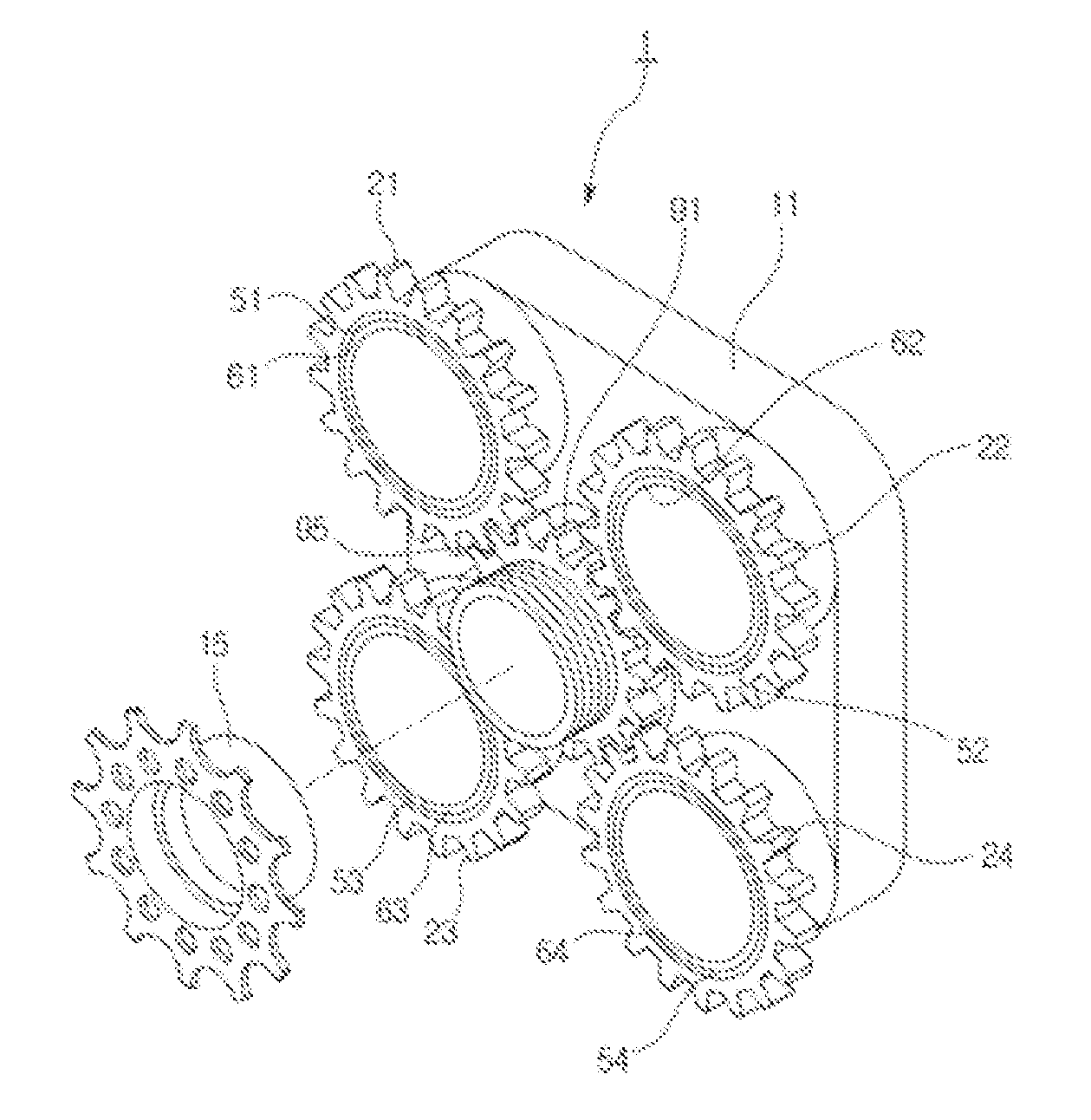
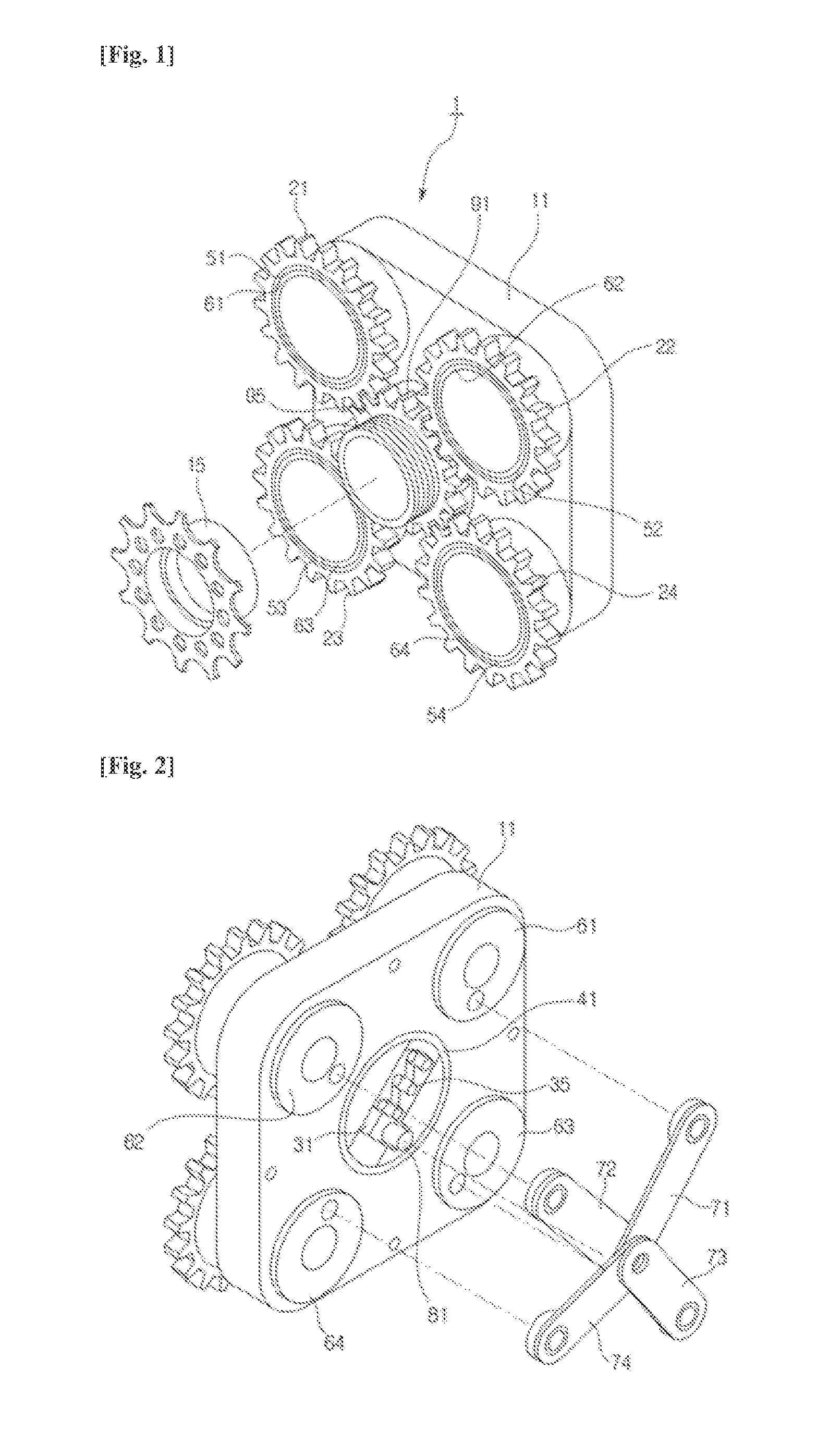
[0029]FIGS. 1 to 3 show the continuously variable transmission apparatus according to the first embodiment of the present invention. As shown therein, the continuously variable transmission apparatus 1 according to the present invention comprises an input shaft 15, a plurality of driven gears 21, 22, 23 and 24, a variable cam 31, a reaction apparatus 35, a variable input link 41, one direction clutches 51, 52, 53 and 54, a plurality of cam shafts 61, 62, 63 and 64, and a plurality of output links 71, 72, 73 and 74.

[0030]The input shaft 15 is rotatably fitted at the frame 11, thus receiving an externally inputted rotational f...


PUM


Abstract

The present invention relates to a continuously variable transmission apparatus, which is characterized by comprising: an input shaft transferred with torque inputted from the outside; a plurality of driven gears which are arranged around the circumference of the input shaft as a certain phase difference and transferred with the power from the input shaft; a variable cam of which the turning radius can be varied by an external load; a variable input link which is coupled to and transferred with the torque of the input haft and allows the rotation thereof; a one-way clutch which is transferred undirectionally with the bidirectional torque to be transferred to the driven gears, respectively, and rotates the driven gears in one direction; a plurality of cam shafts which contact the one-way direction clutch internally or externally; and a plurality of output links, each of which one end revolves together with the variable cam around the center of rotation of the variable input link and the other ends of which are coupled to the cam shafts respectively and allow swiveling thereof.

Description

TECHNICAL FIELD[0001]The present invention relates to a continuously variable transmission apparatus and in particular to a compact-sized continuously variable transmission apparatus in which an instant output torque can automatically increase and decrease depending on the increase and decrease of a load applied to an output shaft.BACKGROUND ART[0002]Decelerator typically is classified into a constant speed decelerator outputting a driving force at a constant deceleration speed in combination with the gears each having different sizes, and a continuously variable transmission changing a deceleration ratio by adapting a conical decelerator.[0003]The rotational force from a driving generation apparatus such as a motor or an engine is outputted at a high rotation speed, but with less torque. In most of industrial machines, a decelerator is typically used, thus augmenting torque.[0004]Here, the decelerator is directed to decelerating the revolutions from a driving force generation appar...

Claims


Application Information

Patent Timeline
IPC IPC(8): F16D13/06
CPCY10T74/151F16H29/04
Inventor SHIN, HYUN WOOSIN, YONG CHOL
Owner SHIN HYUN WOO
Learn More