
Device and arrangement for filling processing stations

a technology for processing stations and devices, applied in the direction of liquid bottling, liquid/fluent solid measurement, containers, etc., can solve the problem that working materials can be easily blown out of the transfer chamber

Inactive Publication Date: 2011-10-20
FASS WOLFGANG +1
View PDF23 Cites 3 Cited by
  • Summary
  • Abstract
  • Description
  • Claims
  • Application Information

AI Technical Summary

Benefits of technology

[0006]By the working material at first transferring from the central tank to a transfer chamber, i.e., a preportioning of the working material is performed so to speak, greater conveying paths can also be accommodated. For this reason, the central tank may be arranged at an easily accessible site as well, such that it can be refilled in a simple manner. Therefore and because of a greater capacity, the central tank can be refilled almost free from contaminations and arranged at a distance from the processing stations, i.e., mainly the heat-sealing stations, such that the risk of injury, especially the risk of getting burned, is avoided. Contaminations that may still possibly occur involve contaminants that pass at a distance from the processing station and can be easily removed. In this case exactly one processing station may be present that is supplied from the central tank. However, the present invention is mainly intended for supplying a plurality of the processing stations, including a heat-sealing means according to the above example, from a common central tank with the working material, granular material of the hot-melt adhesive. In this way, only one more central tank needs to be monitored, as a result of which the operating cost is considerably reduced.
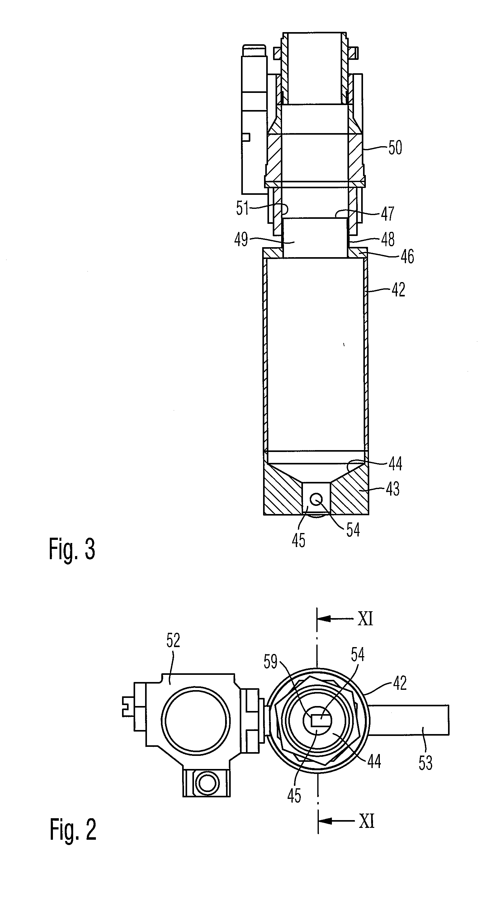
[0008]For this purpose, a bottom surface deepening towards a sump in a funnel-like manner is provided at the bottom of the transfer chamber. The sump may be provided in the center in the bottom of the transfer chamber, but also off-center, for example, laterally. The sump should be embodied as a blind hole and have a diameter that corresponds approximately to the internal diameter of the discharge opening or of the feed tube. Also, as a result of this, the working material can be easily blown out of the transfer chamber. Conveying tracks (paths) of about 100 m and a height difference of up to 25 m can be overcome with such an equipped pilot plant. This alternative embodiment of the transfer chamber is also conceivable independent of the device and arrangement according to the present invention.
[0011]According to a variant of the arrangement according to the present invention, provisions are made that the working material is fed from the transfer chamber at first to a means for separating the pressurizing means, i.e., for example, compressed air, and is conveyed from there in an unpressurized manner into the tank of the processing station. In the prior-art process mentioned in the introduction, in which the granular material of the hot-melt adhesive was conveyed from the drum by means of compressed air into the tank of the processing station, this also led to a cooling of the heat-sealing means. As a result of this, the heat-sealing means was partly cooled below the melting point of the hot-melt adhesive, which led to disturbances in the operating sequence. Since, according to the present variant, the compressed air is already separated beforehand and the working material flows into the tank in an unpressurized manner, this risk is avoided.

Problems solved by technology

Also, as a result of this, the working material can be easily blown out of the transfer chamber.

Method used


Image

  • Device and arrangement for filling processing stations
  • Device and arrangement for filling processing stations
  • Device and arrangement for filling processing stations

Examples


Embodiment Construction

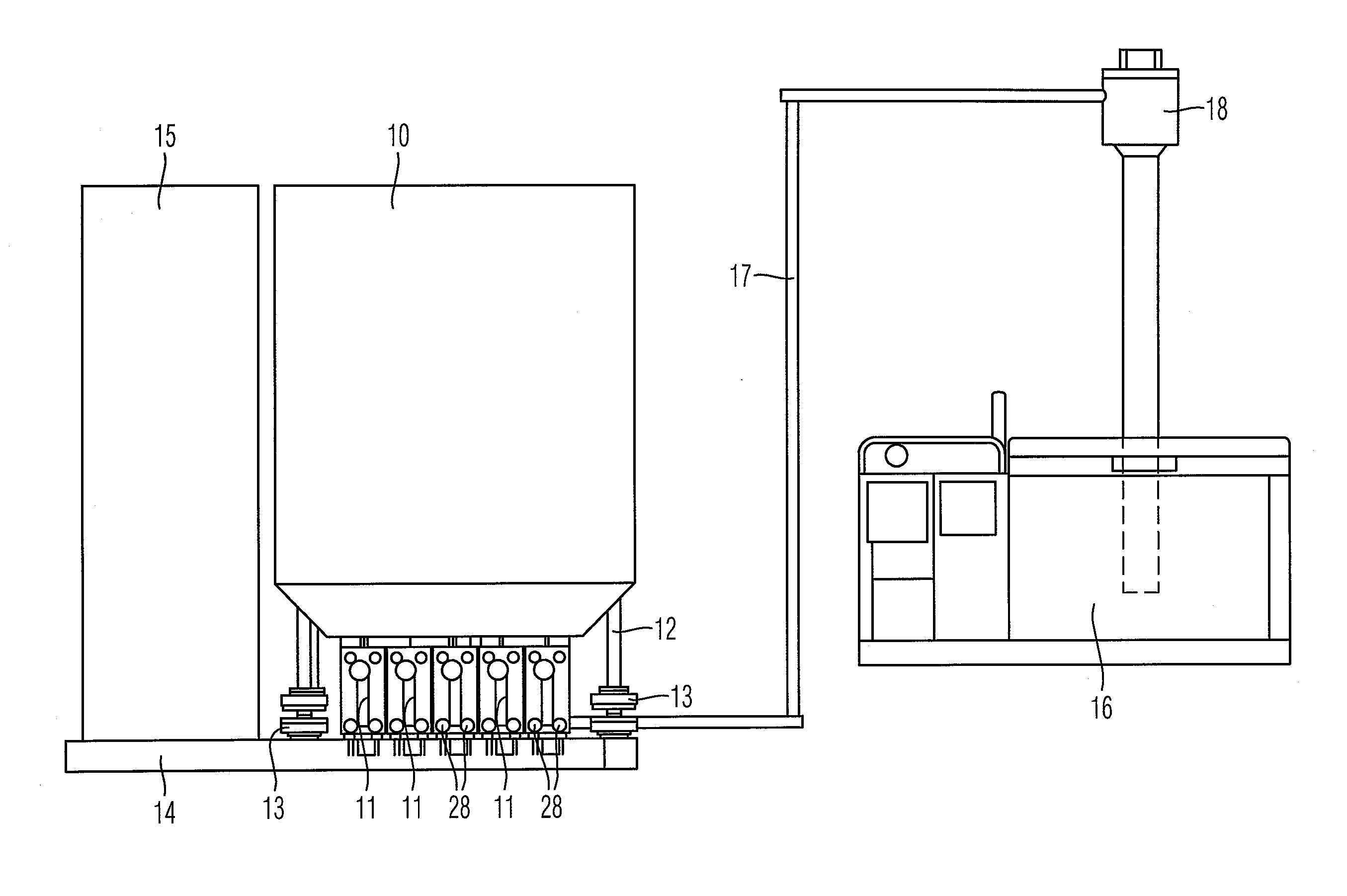
[0021]Referring to the drawings in particular, the arrangement shown in FIG. 1 includes a central tank 10 with transfer cartridges 11 arranged under the central tank. Central tank 10 is mounted on columns 12 by means of vibration dampers 13 on a basic frame 14. Furthermore, a control box 15 for controlling the device is assigned to the central tank 10.

[0022]FIG. 1 shows, as representative of a random number of processing stations, a processing station, in particular a heat-sealing means 16. A working material, a granular material of a hot-melt adhesive in the present case, is fed by means of a feed line 17 at first to a ventilating means 18, the significance of which will still be explained further below. This ventilating means 18 is located above the heat-sealing means 16, specifically above a tank of same, so that the working material can flow in an unpressurized manner from the ventilating means 18 into the tank of the heat-sealing means 16. The feed line 17 is connected to the t...


PUM

PropertyMeasurementUnit
Pressureaaaaaaaaaa
Flow rateaaaaaaaaaa
Diameteraaaaaaaaaa

Abstract

A device for filling processing stations (16) with a pumpable working material guarantees a permanent and sufficient supply of working material to the processing station with the lowest possible expense and greatest possible cleanliness. The device includes a transfer chamber (42) assigned to a central tank (55) for the working material. The transfer chamber (42) is assigned to a processing station (16), in such a way that the working material can be fed at first from the central tank (55) into the transfer chamber (42) and from there to the processing station (16). An arrangement is also provided that includes such a device.

Description

CROSS REFERENCE TO RELATED APPLICATIONS[0001]This application claims the benefit of priority under 35 U.S.C. §119 of European Patent Application EP 10 160 122.7 filed Apr. 16, 2011, the entire contents of which are incorporated herein by reference.FIELD OF THE INVENTION[0002]The present invention pertains to a device for filling processing stations with a pumpable working material (operating substance). The present invention pertains, furthermore, to an arrangement for filling processing stations with a pumpable working material, with a central tank for the working material and with two or more processing stations and a feed line for feeding the working material to one of the processing stations.BACKGROUND OF THE INVENTION[0003]Even though the present invention is suitable for all pumpable working materials, i.e., bulk materials, gel-like or pasty substances or liquids, a concrete application of the present invention is the preparation of hot-melt adhesives for a heat-sealing means,...

Claims


Application Information

Patent Timeline
IPC IPC(8): B65B3/04
CPCB65D90/64G01F11/34B65D90/66G01F13/00
Inventor FASS, WOLFGANGHENKE, ANDREAS
Owner FASS WOLFGANG
Learn More