
Apparatus and method of recognizing presence of objects

Active Publication Date: 2011-10-13
DENSO CORP
View PDF4 Cites 34 Cited by
  • Summary
  • Abstract
  • Description
  • Claims
  • Application Information

AI Technical Summary

Benefits of technology

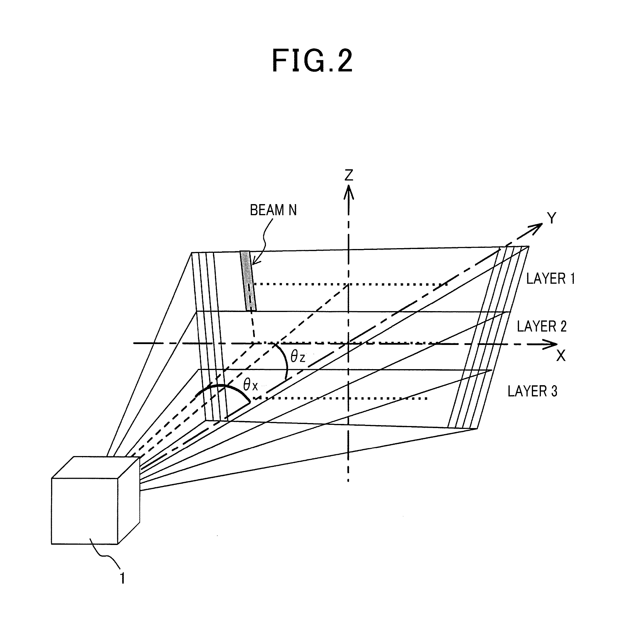
[0016]Thus, according to the object recognition apparatus, focus is put on the characteristics indicated by the detection results of the multiple layers, i.e. distance frequency distribution and reflection intensity frequency distribution in the multiple layers, according to the angle of a road surface. Then, the detection results are processed to reliably make a determination as being of a road surface. In this way, an object can be accurately recognized (or estimated) based on reception signals.
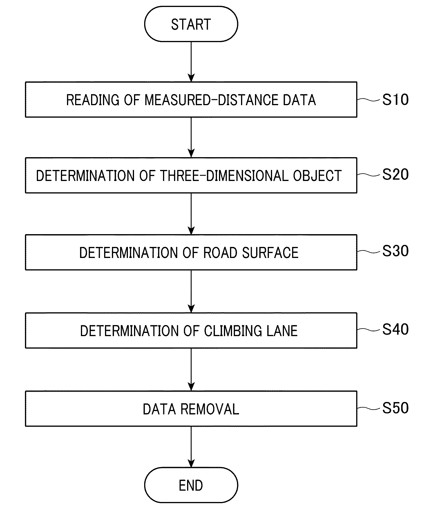
[0018]In this way, even when an object is a climbing lane, which is not a horizontal road surface, accurate object recognition can be performed based on reception signals.

Problems solved by technology

However, the object recognition technique using two-dimensional scan is based on a premise of recognizing three-dimensional objects, such as a preceding vehicle or a roadside object, and thus is not configured to determine whether or not a distance data in question corresponds to the reflection from a road surface.
Therefore, the object recognition technique using two-dimensional scan is not able to distinguish whether or not an acquired datum is the reflected datum obtained from an object (three-dimensional object) or the reflected datum obtained from a road surface.
Accordingly, with this technique, a reflected datum is likely to be erroneously recognized as being the reflected datum obtained from an object in spite of the fact that the reflected datum is of a road surface.
Therefore, reception signals of a reflected wave from a climbing lane (an upward slope) are likely to be erroneously detected as being signals from a three-dimensional object.
Thus, the detection results are unlikely to be erroneously determined when an object is anything other than a road, e.g. when an automobile of about 5-meter long passes over in the forward direction.
Thus, it is unlikely that an erroneous determination is made on detection results obtained from anything other than a road.

Method used


Image

  • Apparatus and method of recognizing presence of objects
  • Apparatus and method of recognizing presence of objects
  • Apparatus and method of recognizing presence of objects

Examples


Embodiment Construction

[0049]With reference to the accompanying drawings, hereinafter will be described an embodiment of the present invention.

[0050]FIG. 1 is a schematic diagram illustrating a general configuration of an object recognition apparatus 1 to which the present invention is applied.

[0051]The object recognition apparatus 1 is installed in a vehicle to recognize (or estimate, detect) an object residing in the forward direction of the vehicle and to generate object data consisting of information (location, size, etc.) associated with the object. The object data generated by the object recognition apparatus 1 is supplied to a vehicle control unit (not shown). The supplied object data is used, for example, for alarm control or so-called inter-vehicle control. Under the alarm control, an alarm is raised if a candidate object is an obstacle residing in a preset alarm area. Under the inter-vehicle control, if a candidate object is a preceding vehicle, the brake, the throttle, the transmission, and the...


PUM


Abstract

An apparatus and method for recognizing presence of an object is provided, the apparatus and method are mounted on or implemented a vehicle. In the apparatus and method, by scanning a beam-shaped electromagnetic wave, data showing reflection intensities of reflected waves and distances between the vehicle and objects outside the vehicle are obtained. Based on the detected data, characteristics presented by frequency distributions of the distances and intensity frequency distributions of the refection intensities obtained in multiple rows in a field of view in the height direction of the vehicle. The characteristics depend on an angle of the electromagnetic wave to a road on which the vehicle travels. It is determined that the characteristics are obtained from the road when the characteristics meet predetermined requirements.

Description

CROSS-REFERENCE TO RELATED APPLICATION[0001]This application is based on and claims the benefit of priorities from earlier Japanese Patent Application Nos. 2010-090790 and 2011-024135 filed Apr. 9, 2010 and Feb. 7, 2011, respectively, the descriptions of which are incorporated herein by reference.BACKGROUND OF THE INVENTION[0002]1. Technical Field of the Invention[0003]The present invention relates to an apparatus and method of recognizing objects which are present outside a vehicle, and in particular, to the apparatus and method that use a technique for transmitting, from the vehicle, electromagnetic waves toward a predetermined field extending in both a widthwise direction (transverse direction) and a heightwise direction (direction vertical to a road surface) of a vehicle, and for recognizing objects based on the reflected electromagnetic waves.[0004]2. Related Art[0005]An object recognition apparatus has been under development, in which transmission waves, such as laser beams or...

Claims


Application Information

Patent Timeline
IPC IPC(8): G01S13/88G01C3/08G01S17/931
CPCG01S7/4802G01S17/936G01S17/42G01S7/4817G01S17/931
Inventor MIYAHARA, TAKAYUKIOGAWA, TAKASHI
Owner DENSO CORP
Learn More