
Pulse-echo method by means of an array-type probe and temperature compensation

a technology of array-type probes and pulse-echo methods, which is applied in the direction of material magnetic measurements, and solid analysis using sonic/ultrasonic/infrasonic waves. it can solve the problem of high temperature-dependent sound velocity of thermoplastic materials used for leading bodies, and achieve easy adaptation of sound emission and accurate determination of sound velocity

Active Publication Date: 2011-10-13
GE SENSING & INSPECTION TECH GMBH
View PDF12 Cites 21 Cited by
  • Summary
  • Abstract
  • Description
  • Claims
  • Application Information

AI Technical Summary

Benefits of technology

[0010]The invention provides an improved pulse-echo method in which the temperature dependence of the sound velocity in the leading body is measured comparatively easily and accurately and, if necessary, compensated in the evaluation of the ultrasound inspection.
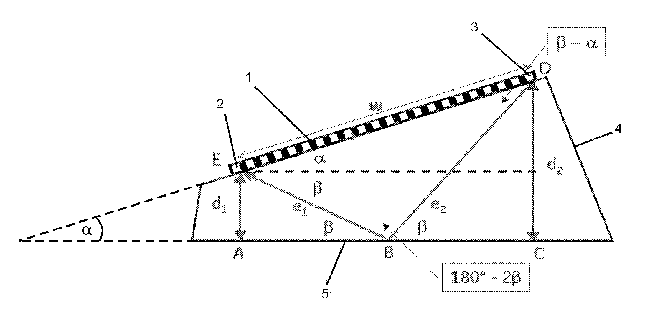
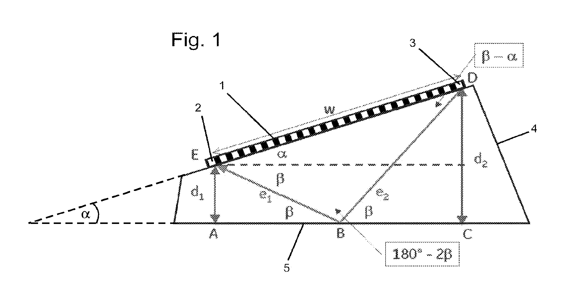
[0013]Several problems can be solved in a simple manner by using a phased array with selectively controllable transducers. By means of selectively using transducers that are spatially as distant from one another as possible as transmitters or receivers, a comparatively long sound path, for example substantially in the direction of the longitudinal direction of the mostly slim leading body, can, on the one hand, be used for determining the sound velocity of the testing sound; the accuracy of the determination of the sound velocity is increased by a sound path that is as long as possible. Therefore, the outermost transducers of the phased array are preferably used in the step for determining the sound velocity, in order to achieve as long a sound path as possible and to increase accuracy.
[0014]On the other hand, using a phased array opens up the possibility, by choosing the location and / or by the number of the selectively controlled transducers, of easily adapting the sound emission to the geometry and / or attenuation of the leading body in such a way that the emitted ultrasonic pulse actually reaches a receiver. Preferably, the phased array therefore comprises more than three selectively controllable transducers. Moreover, a test reflector that interferes with the actual ultrasound inspection is advantageously dispensable. In a simple case, the measurement of the temperature-dependent sound velocity can serve for detecting the overheating of the leading wedge.
[0015]Preferably, the sound velocity of the leading body determined in the step for determining the sound velocity is used in the evaluation of the signals in the ultrasound inspection of the workpiece. As is described in the introduction, the space-dependent representation is linked to the time-dependent representation through the sound velocity varying with the temperature. Therefore, an accurate, almost simultaneous determination of the sound velocity serves for increasing the accuracy of the ultrasound inspection of the workpiece, for example with regard to its dimensions or the positions of the discontinuities contained therein. It should be clear to the person skilled in the art that he is able to enhance the accuracy of the sound velocity determination in the leading body by repeating the step, by reversal of the sound propagation in the process and / or by using further transducers, i.e. sound paths.
[0020]Furthermore, the method comprises at least one step in which the travel time of the back-face echo of the leading body's coupling surface adjoining, or to be adjoined to, the workpiece is determined for at least one of the transducers acting as a transmitter or receiver. That is, the travel time of the ultrasound is additionally determined which is emitted by the at least one transducer that acts in the previously described step as a transmitter or receiver, is reflected on the back face, i.e. the coupling surface, and is received by the same transducer. A manual measurement of this distance can thus be dispensed with. Moreover, an accurate and current determination can thus take place because the dimensions of the leading body, as a rule, are subject to wear-related changes. For example, in the case of a wedge-shaped leading body, the shortest sound path between the transducers can be determined very accurately by means of the distance between the transducers and two travel time measurements of the back-face echo in which the transducer concerned, respectively, acts as a transmitter and a receiver.
[0026]As was already explained above, several problems can be solved in a simple manner by using a phased array with selectively controllable transducers. By means of selectively using transducers that are spatially as distant from one another as possible as transmitters or receivers, a comparatively long sound path (for example substantially in the direction of the longitudinal direction of the mostly slim leading body) can, on the one hand, be used for determining the sound velocity of the testing sound in the leading body; the accuracy of the determination of the sound velocity is increased by a sound path that is as long as possible. On the other hand, using a phased array opens up the possibility, by choosing the location and / or by the number of the selectively controlled transducers, of easily adapting the sound emission to the geometry and / or attenuation of the leading body in such a way that the emitted ultrasound actually reaches a receiver. Preferably, the phased array therefore comprises more than two selectively controllable transducers. Moreover, a test reflector that interferes with the actual ultrasound inspection is advantageously dispensable.

Problems solved by technology

However, it was found that the sound velocity of the thermoplastic material used for the leading body is highly temperature-dependent, at least in comparison with the primarily metallic workpieces that are to be inspected.
This may also lead to errors also in the case of an electronic adjustment of the insonification angle, for example by means of a phased array.

Method used


Image

  • Pulse-echo method by means of an array-type probe and temperature compensation
  • Pulse-echo method by means of an array-type probe and temperature compensation
  • Pulse-echo method by means of an array-type probe and temperature compensation

Examples


Embodiment Construction

[0028]In the preferred embodiment of the method according to the invention, an ultrasound inspection by means of a pulse echo is carried out on a workpiece, which is not shown in FIG. 1, by means of the probe shown in FIG. 1. The phased array 1 of the probe which is also used in the determination of the sound velocity in the leading body 4, as will be described later, is used in this embodiment. The phased array 1 comprises several (in this case 22) selectively controllable sound transducers 2, 3. During the ultrasound inspection, they can be controlled jointly and in phase, but jointly mutually out of phase, selectively in groups etc. The invention is not limited with regard to the process of the ultrasound inspection, and it is the responsibility of the person skilled in the art to select the respectively suitable controlling option. The ultrasound generated by the transducers 2, 3 of the phased array 1 passes through a leading body 4 of thermoplastic material in order to enter th...


PUM

PropertyMeasurementUnit
frequencyaaaaaaaaaa
sound velocityaaaaaaaaaa
thermoplasticaaaaaaaaaa

Abstract

The invention relates to a nondestructive ultrasonic test method in which at least one ultrasonic pulse is emitted into a workpiece under test by means of at least one ultrasonic transmitter (3), the ultrasonic pulse is reflected on boundary surfaces within the workpiece, the reflected ultrasound is received by at least one ultrasonic receiver (2), and the associated signals are evaluated, the ultrasound penetrating a damping block (4) that is arranged between the workpiece and the transmitter or receiver. Said method is characterized in that it includes at least one step for determining the sound velocity in the damping block (4) by means of an array-type probe (1) comprising selectively controllable transducers; in said step, at least one first transducer (3) of the array-type probe (1) is used as the transmitter of at least one ultrasonic pulse, while at least one second transducer (2) of the array-type probe (1) is used as the receiver of the ultrasonic pulse, and the sound velocity in the damping block (4) is determined at least by measuring the propagation time of the ultrasound along the shortest distance (e1, e2) of the ultrasound between the respective transducers (2, 3) that are placed at a distance from each other.

Description

TECHNICAL FIELD[0001]The invention relates to a pulse-echo method for ultrasound material inspection and a device therefor. This is an acoustic method for finding material flaws in which ultrasound is used. Ultrasound testing belongs to the non-destructive testing methods. In this manner, components can be inspected also in the fitted state, e.g. the supporting members of an airplane. Ultrasound testing is a suitable testing method for finding internal and external flaws in sound-conducting materials (to which most metals belong), for example in welding seams, forgings, cast, semi-finished products or pipes. In mechanical engineering, quality control of components is an important task in order to ensure, for example, the safety of passenger transport devices or of pipelines, for example for hazardous substances. Laid railroad tracks are routinely inspected by test trains. Therefore, the enhancement of the reliability and accuracy of these methods is intended.BACKGROUND[0002]Like all...

Claims


Application Information

Patent Timeline
Patent Type & Authority Applications(United States)
IPC IPC(8): G01N29/07
CPCG01N29/07G01N29/221G01N29/326G01N29/2487G01N29/262G01N29/2468
Inventor OBERDOERFER, YORKBERKE, MICHAELKLEINERT, WOLF-DIETRICHPOIRIER, JEROMESCHIEKE, SASCHA
Owner GE SENSING & INSPECTION TECH GMBH
Learn More