Lens barrel and imaging device

a technology of lens barrel and imaging device, which is applied in the field of lens barrel, can solve the problems of affecting the compactness affecting the efficiency of the lens barrel, and the size so as to achieve the effect of simplifying the structure of the focus lens unit and its surrounding parts, compactness, and compactness

Active Publication Date: 2011-10-06
PANASONIC CORP
View PDF1 Cites 10 Cited by
  • Summary
  • Abstract
  • Description
  • Claims
  • Application Information

AI Technical Summary

Benefits of technology

[0012]In view of this, the inventors of the present invention studied a lens barrel with which drive of the zoom mechanism is performed only by manual operation by the user, and drive of the focus lens unit with respect to the zoom mechanism is performed only by actuator. In this case, the structure of the focus lens unit and its surrounding parts is simplified, so the focus lens unit can be made more compact.
[0013]However, if a motor is used as the actuator that drives the focus lens, when the motor is attached to the lens barrel, the motor sticks out considerably to the outside of the lens barrel, and this hampers the effort to make the lens barrel more compact.
[0015]With this lens barrel, when viewed in the optical axis direction, the drive unit is fixed to the first lens unit so that a first profile line formed by the first lens unit and the drive unit is substantially circular, so the drive unit does not stick as far outside from the first lens unit. This allows the lens barrel to be more compact. Also, a reduction in size is possible with an imaging device equipped with this lens barrel.

Problems solved by technology

However, if a configuration is employed in which the focus lens unit is driven in the optical axis direction by a cam mechanism, as with the lens barrel described in Japanese Laid-Open Patent Application 2006-113289, the size of the focus lens unit becomes larger, or the weight of the focus lens unit increases.
However, if a motor is used as the actuator that drives the focus lens, when the motor is attached to the lens barrel, the motor sticks out considerably to the outside of the lens barrel, and this hampers the effort to make the lens barrel more compact.

Method used


Image

  • Lens barrel and imaging device
  • Lens barrel and imaging device
  • Lens barrel and imaging device

Examples


first embodiment

[0040]Summary of Digital Camera

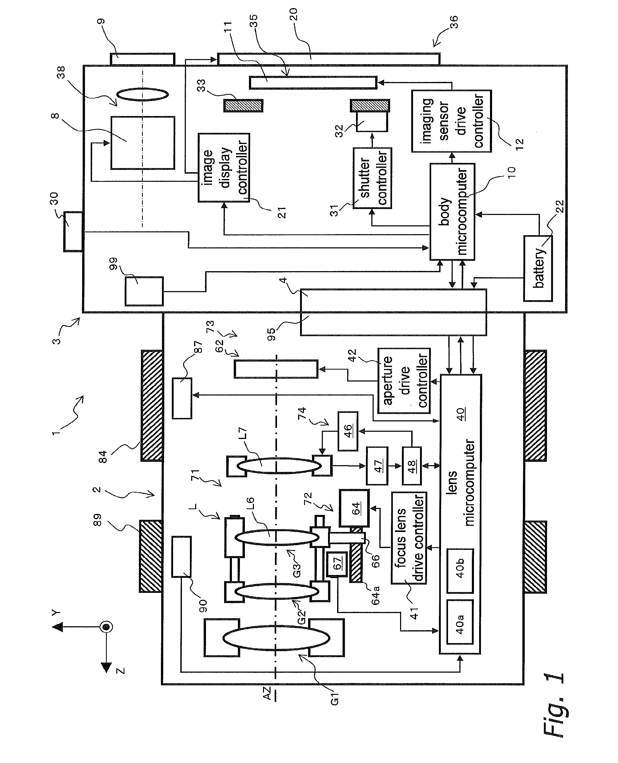
[0041]A digital camera 1 will be described through reference to FIGS. 1 to 14. FIG. 1 is a simplified diagram of the digital camera 1. As shown in FIG. 1, the digital camera 1 (an example of the imaging device) is a digital camera with an interchangeable lens, and mainly comprises a camera body 3 and an interchangeable lens unit 2 (an example of the lens barrel) that is removably mounted to the camera body 3. The interchangeable lens unit 2 is mounted via a lens mount 95 to a body mount 4 provided to the front face of the camera body 3.

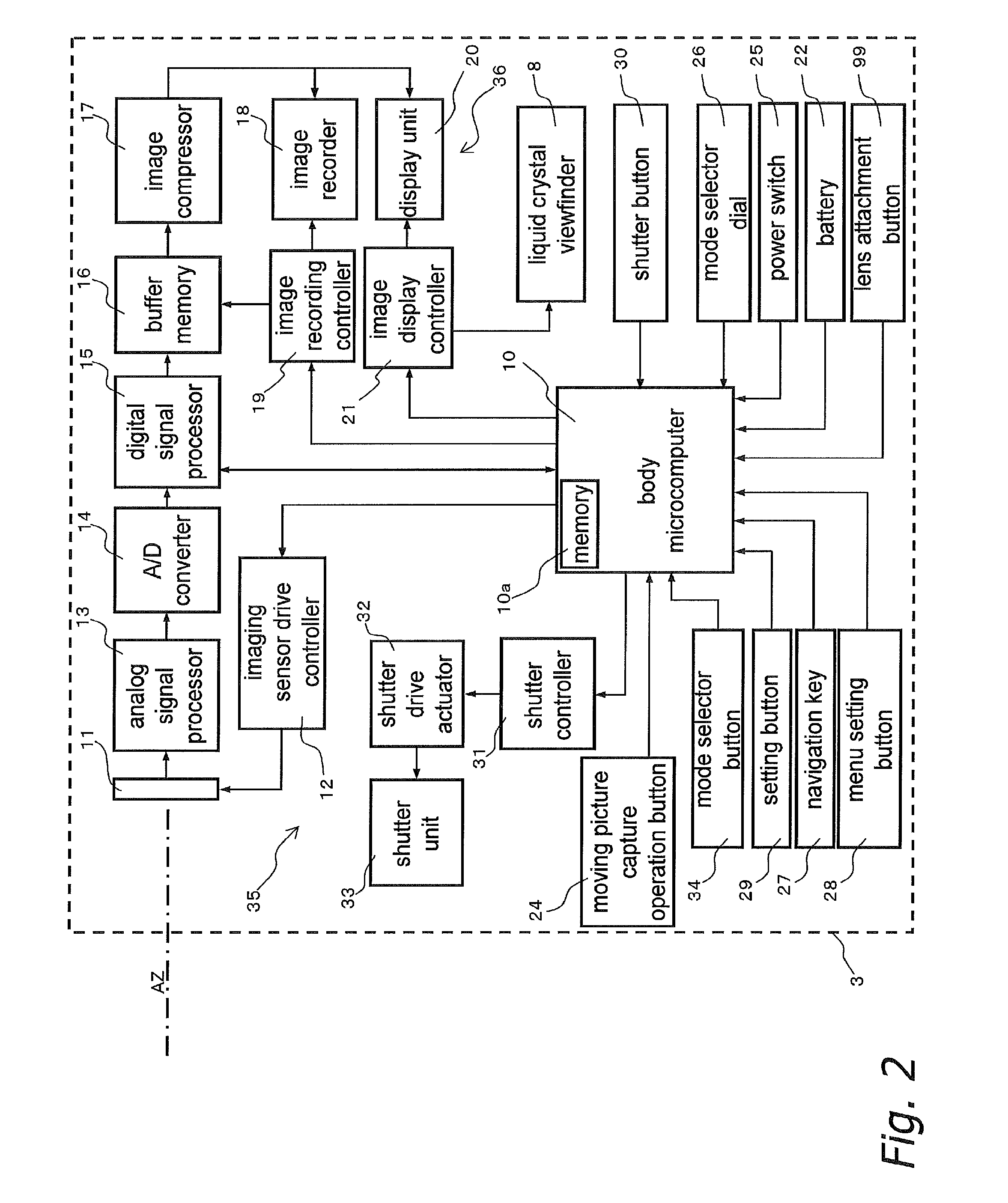
[0042]FIG. 2 is a block diagram of the configuration of the camera body 3. FIG. 3 is a simplified oblique view of the digital camera 1. FIG. 4A is a top view of the camera body 3, and FIG. 4B is a rear view of the camera body 3. FIGS. 5 to 8 are simplified cross sections of the interchangeable lens unit 2. FIGS. 5 and 6 show the state at the wide angle end, and FIGS. 7 and 8 show the state at the telephoto end. FIG. 6 is...


PUM


Abstract

The lens barrel includes a first lens unit, a second lens unit, and a drive unit. The first lens unit includes a first lens element and a first lens support frame supporting the first lens element. The second lens unit includes a second lens element and a second lens support frame supporting the second lens element. The second lens unit is supported by the first lens unit to be movable in the optical axis direction of the first lens element with respect to the first lens unit. The drive unit is arranged to be used to drive the second lens unit with respect to the first lens unit, and is fixed to the first lens unit. When viewed in the optical axis direction, the drive unit is fixed to the first lens unit so that a first profile line formed by the first lens unit and the drive unit is substantially circular.

Description

CROSS-REFERENCE TO RELATED APPLICATIONS[0001]This application claims priority to Japanese Patent Application No. 2008-230163 filed on Sep. 8, 2008. The entire disclosure of Japanese Patent Application No. 2008-230163 is hereby incorporated herein by reference.BACKGROUND[0002]1. Technical Field[0003]The technical field relates to a lens barrel with which the focal length can be changed.[0004]2. Description of the Related Art[0005]Conventional digital cameras make use of a zoom lens system with which the focal length can be varied while the object distance of a subject that is in focus (hereinafter also referred to as the subject distance) is kept substantially constant. For example, zoom lens systems are employed in compact digital cameras and digital cameras with interchangeable lenses.[0006]With a conventional lens barrel, for example, as the zoom mechanism operates, the focus lens unit including the focus lens is moved in the optical axis direction by a cam mechanism. This allows ...

Claims


Application Information

Patent Timeline
Patent Type & Authority Applications(United States)
IPC IPC(8): H04N5/225G02B15/14
CPCG02B7/102G02B15/173H04N5/23296H04N5/23212H04N5/23209G02B15/144109H04N23/55H04N23/663H04N23/673H04N23/631H04N23/69
Inventor YUMIKI, NAOTOONISHI, HIDEOARAKI, YOSHIHARUMURAMATSU, FUMIO
Owner PANASONIC CORP
Why Eureka
Try Eureka