Control device for vehicular power transmitting system and corresponding method

a control device and transmission system technology, applied in the direction of rotary clutches, couplings, fluid couplings, etc., can solve the problems of increasing the internal loss of the torque converter, the inability to rapidly generate driving force, and the limitation of the concurrent improvement of fuel efficiency and driving performance, so as to reduce the amount of heat

Inactive Publication Date: 2011-10-06
TOYOTA JIDOSHA KK
View PDF2 Cites 7 Cited by
  • Summary
  • Abstract
  • Description
  • Claims
  • Application Information

AI Technical Summary

Benefits of technology

[0009]In the control device according to the first aspect of the invention, the capacity coefficient control unit increases the capacity coefficient of the torque converter based on the amount of heat generated during slip control of the lock-up clutch, so as to reduce torque assigned to the lock-up clutch (i.e., torque to be transferred by the lock-up clutch) and suppress or avoid increase in the amount of heat generated in the lock-up clutch. Accordingly, the slip control is easily implemented in a running region in which the slip control was difficult to carry out as the amount of heat generated in the lock-up clutch increases. Thus, the running region in which the slip control is effected can be expanded, which leads to an improvement in the fuel efficiency.
[0011]With the control device as described above, the amount of heat generated during slip control of the lock-up clutch is reduced or prevented from increasing, and therefore, the slip control region can be expanded.
[0018]With the control device as described above, the slip control region of the lock-up clutch can be expanded while avoiding reduction in the durability of the lock-up clutch.
[0021]The capacity coefficient control unit may cause the electric motor to rotate the stator wheel in a reverse direction so as to increase the capacity coefficient of the torque converter. In this manner, the capacity coefficient can be easily increased.
[0023]Also, the stator wheel may be coupled to the non-rotary member when appropriate, so that the torque converter operates in substantially the same manner as the torque converter of the related art. In a torque converter range, for example, the stator wheel is inhibited from rotating so as to amplify or increase the torque. In a coupling range, on the other hand, the braking means is released so as to rotate the stator wheel at idle, thereby to avoid reduction in the transmission efficiency clue to collision of hydraulic oil against the stator wheel.
[0024]Also, the vehicular power transmitting system may further include a clutch that selectively couples the electric motor and an output shaft of the torque converter. With this arrangement, when the electric motor is coupled to the output shaft of the torque converter, the electric motor is able to function as a driving source for driving the vehicle or regenerating electrical energy.

Problems solved by technology

Thus, there is a limit to the concurrent improvements of the fuel efficiency and the driving performance.
Therefore, if the driver depresses the accelerator pedal while the vehicle is running in a steady state, so as to accelerate the vehicle, the rotational speed of the turbine wheel is not raised unless the transmission is shifted down, and therefore, the driving force cannot be rapidly generated.
In this case, however, a difference between the rotational speed of the pump impeller (pump speed) and the rotational speed of the turbine wheel (turbine speed) is large even during steady-state running of the vehicle, and the internal loss of the torque converter is increased.
However, if the slip control is effected in a running region in which the input torque transmitted to the lock-up clutch is large, for example, the amount of heat generated from the lock-up clutch is increased, resulting in a problem of reduction in the durability of the lock-up clutch.
If the slip amount is reduced, however, a vibration damping effect inherently provided by the torque converter is reduced, which may result in an increase of the booming noise.
Thus, the expansion of the slip control region of the lock-up clutch is limited so as to prevent the increase in the generated heat amount of the lock-up clutch and the reduction in the durability.

Method used


Image

  • Control device for vehicular power transmitting system and corresponding method
  • Control device for vehicular power transmitting system and corresponding method
  • Control device for vehicular power transmitting system and corresponding method

Examples


Embodiment Construction

[0040]One embodiment of the invention will be described in detail with reference to the drawings. A system of the embodiment as described below is simplified or altered as needed in the drawings, and parts or components of the system are not necessarily depicted with accuracy in terms of the ratio of dimensions among the parts, shapes, and so forth.

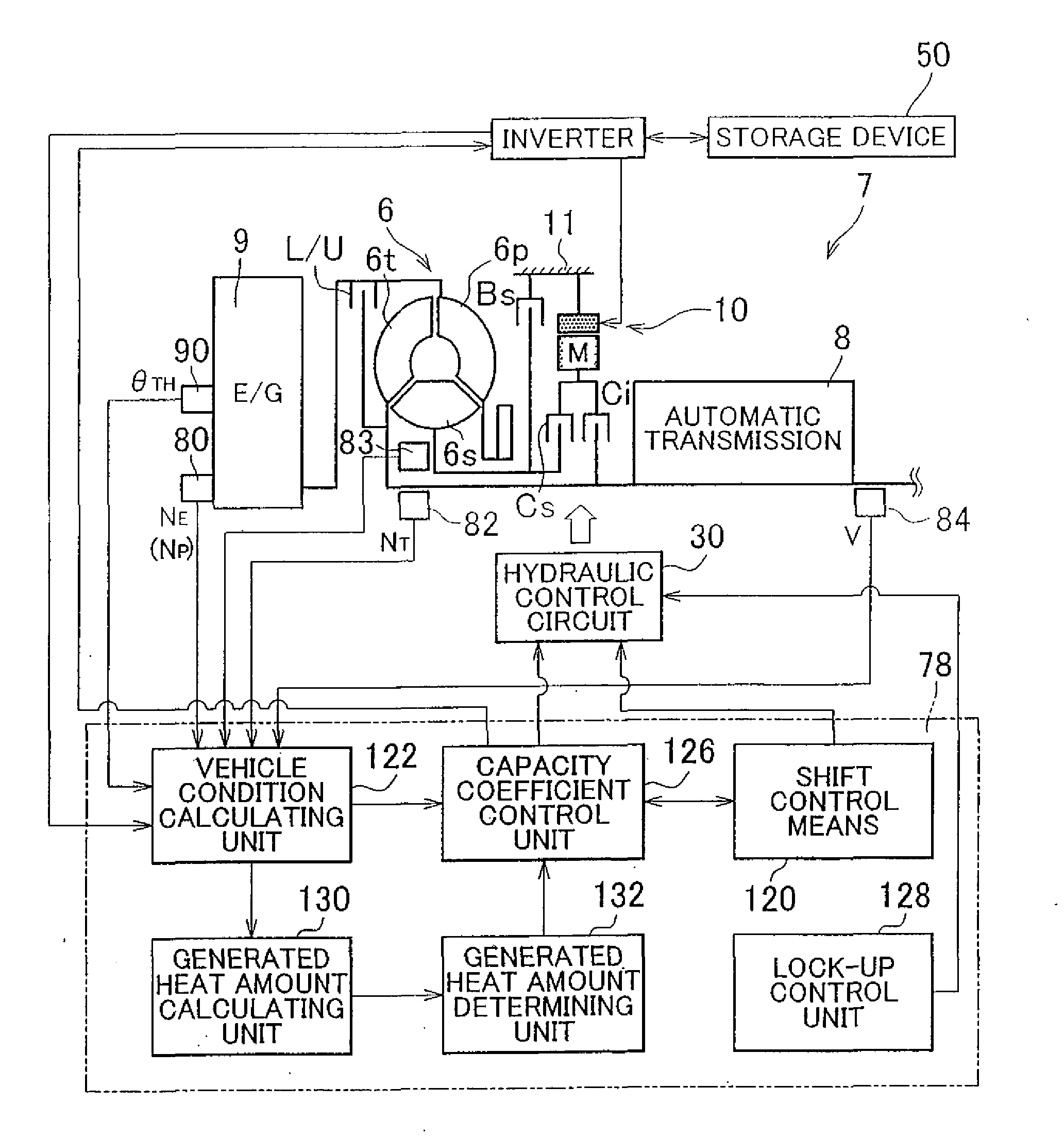
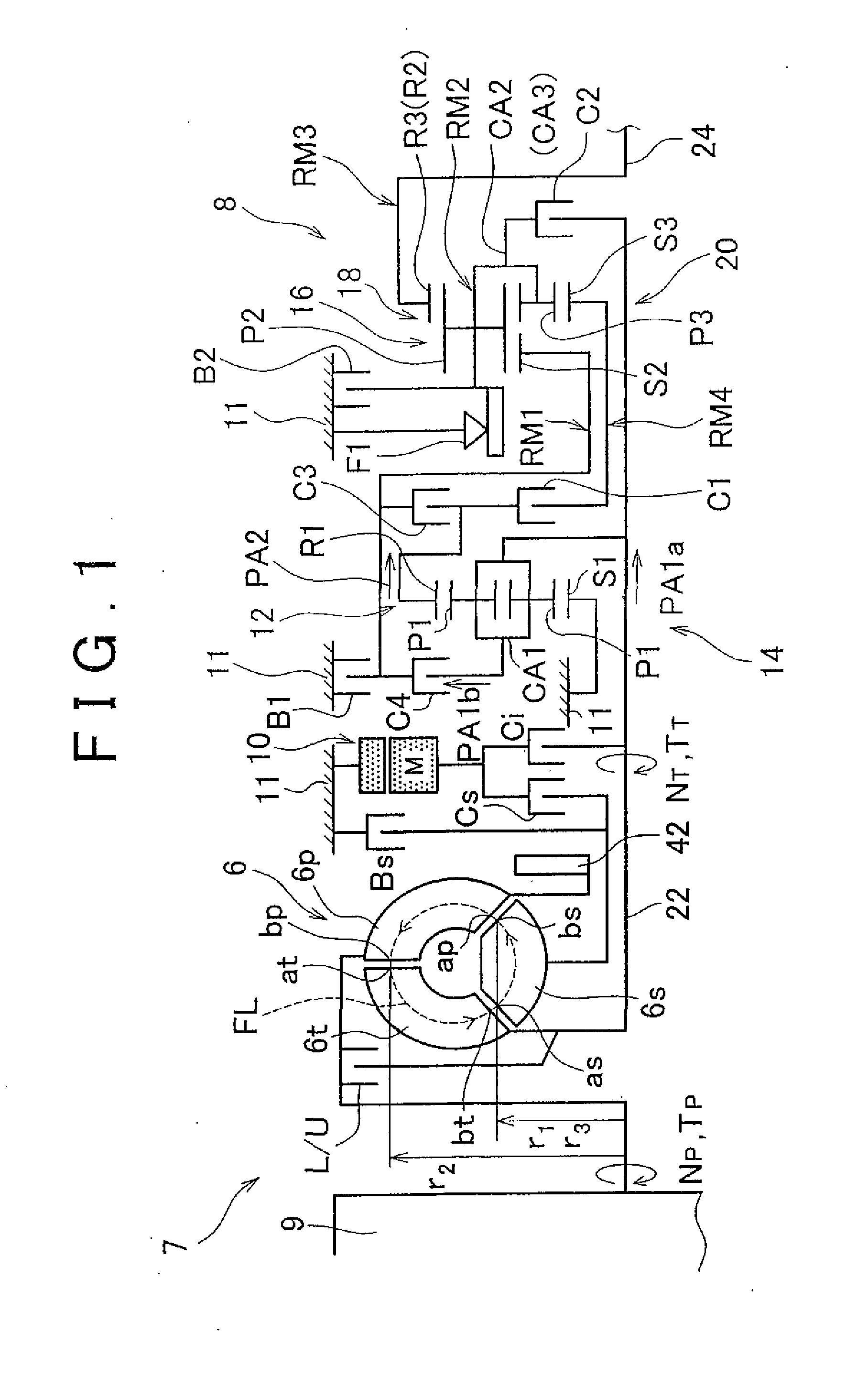
[0041]FIG. 1 is a skeleton diagram of a vehicular power transmitting system 7 in which a torque converter 6 (variable capacity type torque converter) according to one embodiment of the invention is used. The vehicular power transmitting system 7 has a longitudinally-installed automatic transmission 8, and is favorably employed in a FR (front engine rear drive) vehicle. The vehicle having the power transmitting system 7 includes an engine 9 as a driving power source for running the vehicle. The output of the engine 9 in the form of an internal combustion engine is transmitted to right and left drive wheels, via a torque converter 6 that fu...


PUM


Abstract

A control device for a vehicular power transmitting system including a torque converter (6) having a pump impeller (6p), a turbine wheel (6t), a stator wheel (6s) rotatably disposed between the turbine wheel and the pump impeller, and a lock-up clutch (L / U) includes a capacity coefficient control unit (126) that controls a capacity coefficient of the torque converter by controlling rotation of the stator wheel, and the capacity coefficient control unit increases the capacity coefficient of the torque converter based on an amount of heat generated during slip control of the lock-up clutch.

Description

FIELD OF THE INVENTION[0001]The invention relates to a control device for a vehicular power transmitting system including a torque converter having a lock-up clutch, and more particularly to control for expanding a range of a slip control region of the lock-up clutch.BACKGROUND OF THE INVENTION[0002]A torque converter having a pump impeller, a turbine wheel, and a stator wheel rotatably disposed between the turbine wheel and the pump impeller is well known in the art. In the toque converter, the stator wheel is coupled to a non-rotary member via a one-way clutch, and the capacity of the torque converter is not variable. Generally, it is desired that the torque converter has a high capacity (capacity coefficient) as its fluid characteristic when it aims at improving the fuel efficiency or reducing fuel consumption. With the above arrangement, however, the capacity of the torque converter is uniquely determined based on the shapes of the pump impeller, turbine wheel and the stator whe...

Claims


Application Information

Patent Timeline
IPC IPC(8): F16H61/50
CPCY02T10/6221B60W10/08B60K6/48F16H2061/145F16H2059/465B60W10/023Y10T477/755F16H61/50F16H2059/467B60K6/387B60W10/115B60L15/2054B60L2240/36B60L2240/421B60L2240/423B60L2240/441B60L2240/443B60L2240/507Y02T10/72Y02T10/62Y02T10/64
Inventor FUJIKANE, TSUYOSHISHIIBA, KAZUYUKIMETSUGI, HIROMITSUTAKEDA, HIROKI
Owner TOYOTA JIDOSHA KK
Why Eureka
Try Eureka