Air bubble recovery device of ship
a technology of air bubble recovery and ship body, which is applied in the field of friction resistance reduction of ships, can solve the problems of increasing the vibratory force of propellers, reducing propulsion efficiency, etc., and achieves the effects of preventing air bubbles, and reducing the frictional resistance of the ship body
- Summary
- Abstract
- Description
- Claims
- Application Information
AI Technical Summary
Benefits of technology
Problems solved by technology
Method used
Image
Examples
first embodiment
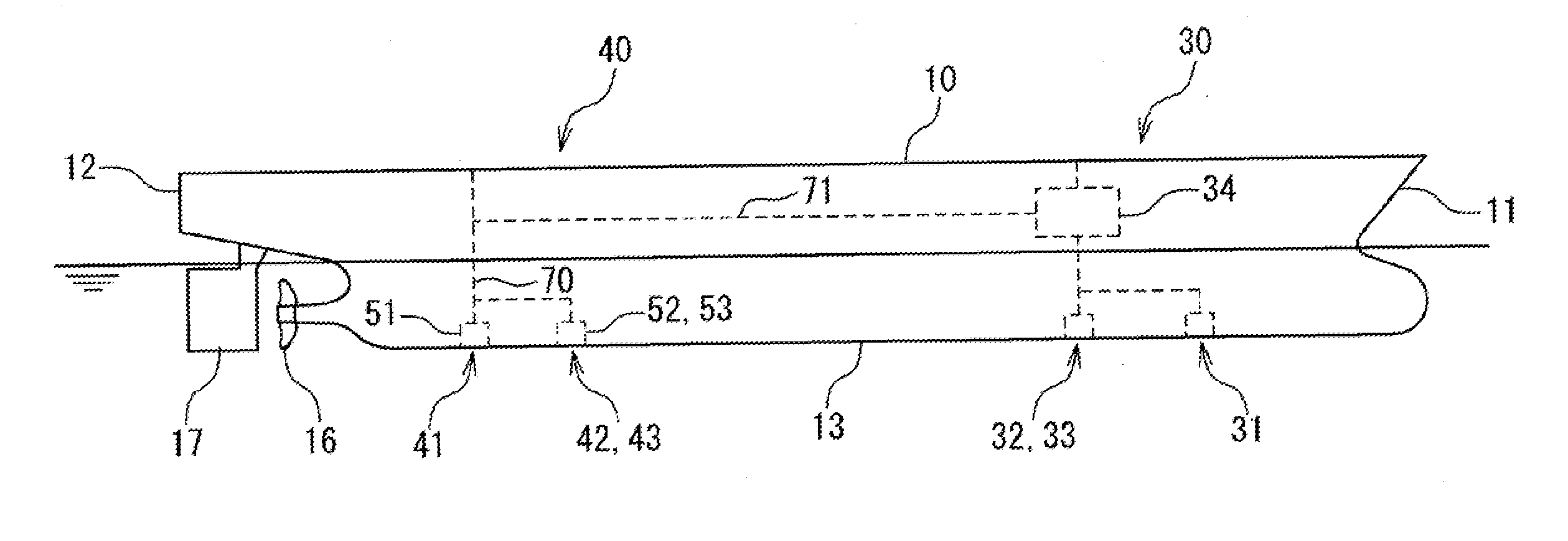
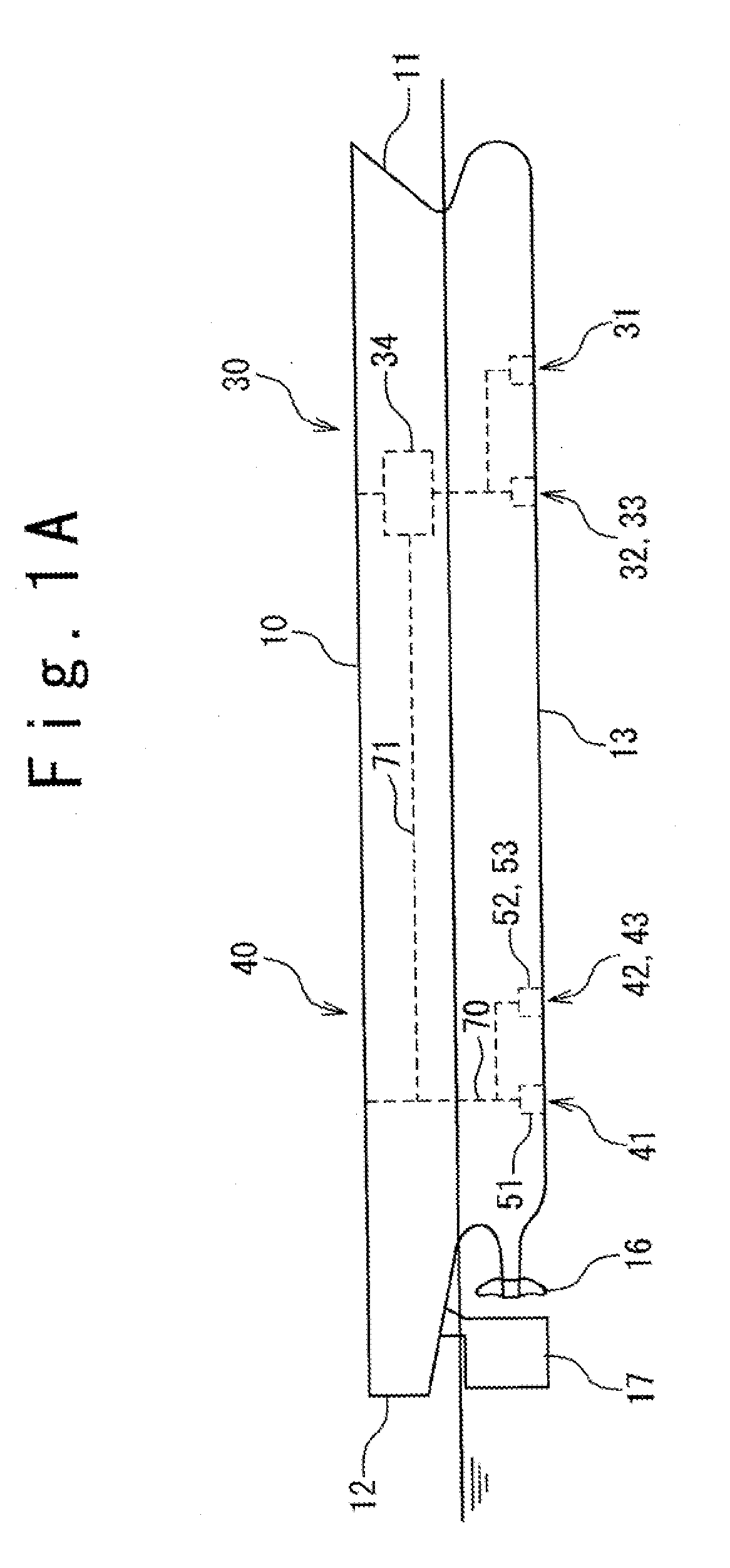
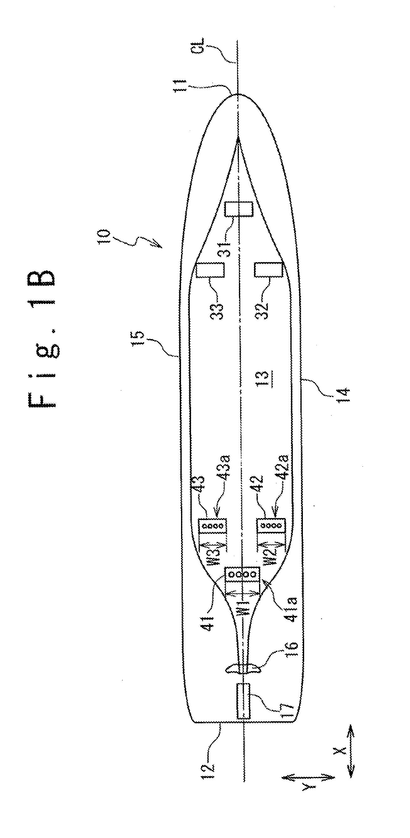
[0030]With reference to FIG. 1A, the frictional resistance reduced ship according to the first embodiment of the present invention has a ship body 10, an air ejecting unit 30 provided to the ship body 10, and an air recovery device 40 provided in the ship body 10. The ship body 10 has a bow 11, a stern 12, a ship bottom 13, a propeller 16, and a helm 17.
[0031]The air ejecting unit 30 has air ejecting outlets 31 to 33 provided on the side of the bow 11 of the ship bottom 13, and a compressor or a blower 34.
[0032]The air recovery device 40 has air recovery inlets 41 to 43 provided on the side of the stern 12 of the ship bottom 13, air recovery chambers 51 to 53, and a flow passage 70. The air recovery chambers 51 to 53 have a gas-liquid separation function. For example, it is possible to apply a gas-liquid separation chamber disclosed in Japanese Patent Publication JP 2009-248831A to the air recovery chambers 51 to 53. The air recovery chambers 51 to 53 can be referred to as gas-liqui...
second embodiment
[0043]With reference to FIG. 3, the frictional resistance reduced ship according to a second embodiment of the present invention is the same as the frictional resistance reduced ship according to the first embodiment, excluding the following points. A port-side air recovery inlet 42 and a starboard-side air recovery inlet 43 are formed in a belt-like shape extending obliquely with respect to a ship length direction X, so that the respective ends of the port-side air recovery inlet 42 and the starboard-side air recovery inlet 43 on the side of the stern 12 are nearer to a center line CL and the other ends on the side of the bow 11 are far from the center line CL.
[0044]According to the present embodiment, the ends nearer to the propeller 16, of the port-side air recovery inlet 42 and the starboard-side air recovery inlet 43 are positioned near to the center line CL, thereby preventing air bubbles from being taken in the propeller 16.
third embodiment
[0045]With reference to FIG. 4, the frictional resistance reduced ship according to a third embodiment of the present invention will be described. The frictional resistance reduced ship according to the present embodiment is the same as the frictional resistance reduced ship according to the first embodiment, excluding the following point. In the present embodiment, the air recovery chambers 51 to 53 do not have a gas-liquid separation function, and the air recovery device 40 has a single gas-liquid separation chamber 55. Seawater which includes the air bubbles, flows into the gas-liquid separation chamber 55 through the air recovery inlet 41 to 43. The gas-liquid separation chamber 50 separates the air from the seawater. The air as a result of the separation is emitted to the atmosphere through the flow passage 70, or supplied to the compressor or the blower 34 through the flow passage 71.
PUM
 Abstract
Description
Claims
Application Information
 - R&D
- Intellectual Property
- Life Sciences
- Materials
- Tech Scout
- Unparalleled Data Quality
- Higher Quality Content
- 60% Fewer Hallucinations
Browse by: Latest US Patents, China's latest patents, Technical Efficacy Thesaurus, Application Domain, Technology Topic, Popular Technical Reports.
© 2025 PatSnap. All rights reserved.Legal|Privacy policy|Modern Slavery Act Transparency Statement|Sitemap|About US| Contact US: help@patsnap.com


