
Bioimaging method using near-infrared (NIR) fluorescent material

a fluorescent material and near-infrared technology, applied in the field of bioimaging markers, can solve the problems of difficult to identify the site marked by tattoo injection from outside the colon/rectum, shallow observation depth, and difficult to detect visible light generated

Inactive Publication Date: 2011-09-29
RIKEN +2
View PDF4 Cites 17 Cited by
  • Summary
  • Abstract
  • Description
  • Claims
  • Application Information

AI Technical Summary

Benefits of technology

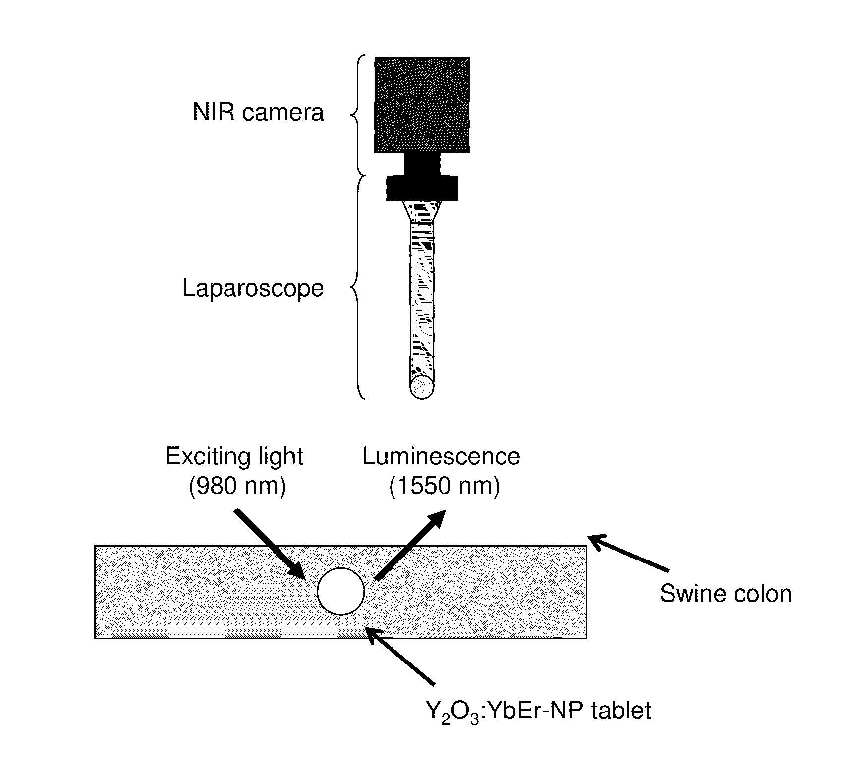
"The present invention provides a new technique for imaging deep into a living body using NIR light and a new method for marking abnormal tissues. The invention involves using a fluorescent material that can be doped into a ceramic with rare earth ions and other elements to penetrate the body. The marker emits NIR fluorescence when exposed to NIR excitation light, which can be detected using a near-infrared light imaging system. The system can be used to visualize the marker introduced into a living body and to diagnose abnormal tissues. The technical effects of the invention include improved imaging depth and accuracy in identifying abnormal tissues."

Problems solved by technology

However, it has been difficult to detect visible light generated as a result of upconversion luminescence from a site deep within a living body because of the influence of light scattering.
Therefore, the observation depth is shallow in cases of NIR-VIS imaging techniques, which has been significantly problematic.
Thus, it may be difficult to identify the site marked by tattoo injection from outside the colon / rectum (i.e., from the serosal side) during surgery due to dispersion of ink or fake tattoo.
Therefore, it is impossible to clearly determine the lesion area during surgery, requiring resection of an organ / tissue area greater than the actual lesion area.
This imposes significant burdens on patients.

Method used


Image

  • Bioimaging method using near-infrared (NIR) fluorescent material
  • Bioimaging method using near-infrared (NIR) fluorescent material
  • Bioimaging method using near-infrared (NIR) fluorescent material

Examples


examples

Preparation of NIR Biophotonic Nanoparticle

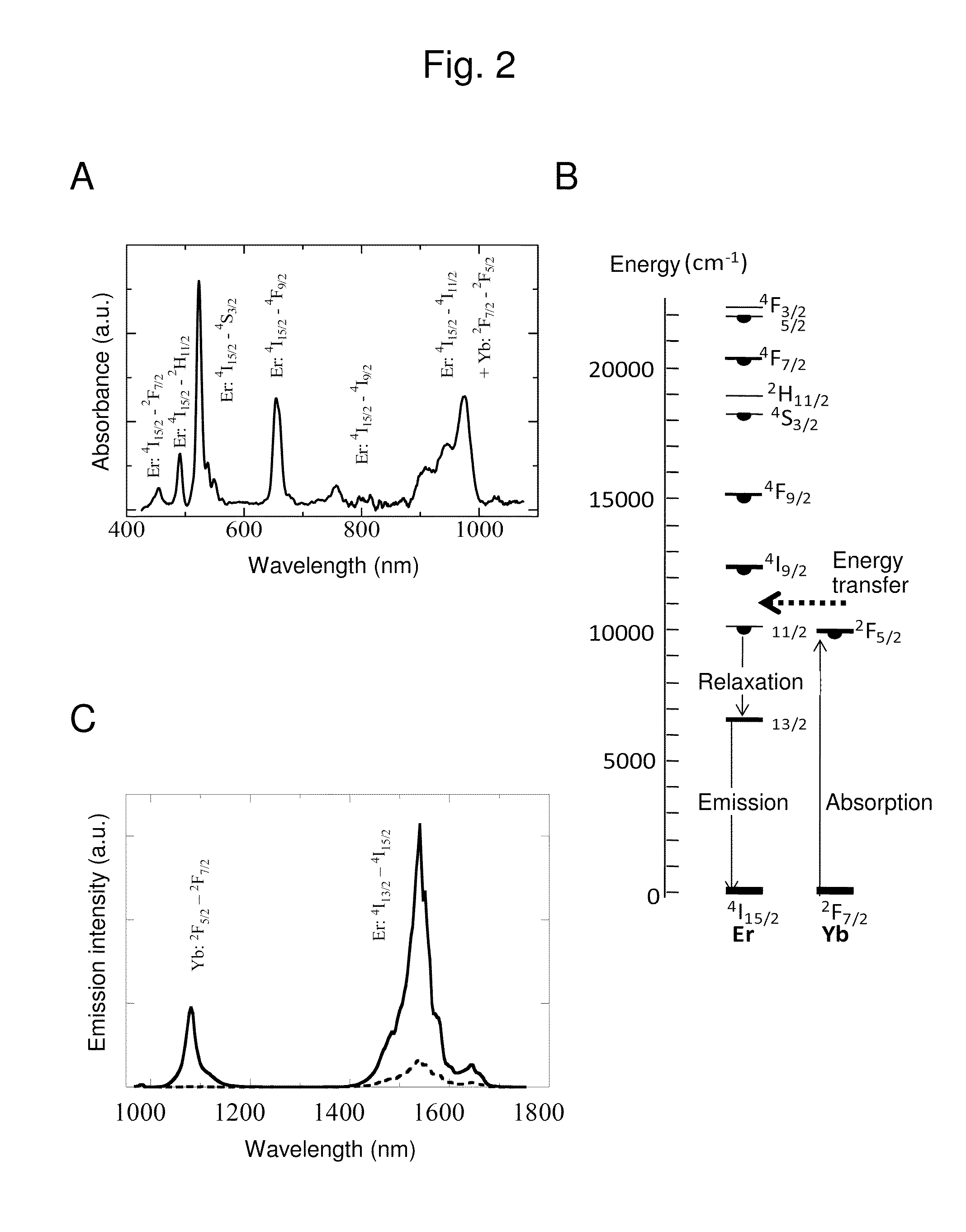
[0086]A fluorescent material was prepared by a known technique used for preparation of an upconversion nanoparticle; that is to say, the homogenous precipitation method (Venkatachalam, N. et. al., Journal of the American Ceramic Society 92, 1006-1010, (2009)). Specifically, 20 mmol / L Y (NO3)3, 0.2 mmol / L Yb (NO3)3, and 0.2 mmol / L Er (NO3)3 were dissolved in purified water (200 mL), mixed with a 4 mol / L urea solution (100 mL), and stirred at 100° C. for 1 hour. The obtained precipitate was separated by centrifugation and dried at 80° C. for 12 hours. The thus obtained precursor was calcinated at 1200° C. for 60 minutes in an electric furnace. Accordingly, anhydrous crystalline Y2O3 nanoparticle codoped with anhydrous crystalline Yb and Er (hereafter referred to as “Y2O3:YbEr-NP”) was obtained.

[0087]The obtained Y2O3:YbEr-NP was identified using a field emission scanning electron microscope (FE-SEM) and X-ray diffraction (XRD). FIGS. 1 (A) an...


PUM

PropertyMeasurementUnit
wavelength rangeaaaaaaaaaa
particle sizeaaaaaaaaaa

Abstract

This invention provides a novel bioimaging technique that can achieve a deep observation depth and a novel method for marking a lesion that allows clear recognition of the lesion from outside a living body. This invention also provides a bioimaging marker comprising a fluorescent material obtained by doping a ceramic with rare earths and the like and a bioimaging technique comprising detecting near-infrared fluorescence that can sufficiently penetrate a living body generated upon excitation of the marker with near-infrared excitation light.

Description

CROSS REFERENCE TO RELATED APPLICATIONS[0001]This non-provisional application claims the benefit under 35 USC §119(e) of U.S. Provisional Application No. 61 / 317,442 filed on Mar. 25, 2010. The entire contents of the above application is hereby incorporated by reference into the present application.BACKGROUND OF THE INVENTION[0002]1. Field of the Invention[0003]The present invention relates to a bioimaging marker comprising a fluorescent material obtained by doping a ceramic with rare earths and the like. The present invention also relates to a bioimaging system and a bioimaging method using the bioimaging marker.[0004]2. Background Art[0005]Bioimaging techniques have been gaining attention recently as tools for observation of biological phenomena both in vivo and in vitro in the field of biomedical research. In particular, there have been many attempts to apply near-infrared (hereafter referred to as “NIR”) light to biomedical photonics within the wavelength range from 800 to 2000 n...

Claims


Application Information

Patent Timeline
Patent Type & Authority Applications(United States)
IPC IPC(8): A61B6/00G01J1/58
CPCA61B5/0071A61B5/0077A61B19/54A61B2019/5412G01N2021/6439A61B2019/5491G01N21/6428G01N21/6456A61B2019/5441A61B90/39A61B2090/3912A61B2090/3941A61B2090/3991
Inventor ZAKO, TAMOTSUMAEDA, MIZUOSOGA, KOHEIKISHIMOTO, HIDEHIROHYODO, HIROSHIITO, MASAAKIKANEKO, KAZUHIRO
Owner RIKEN
Learn More