Axial Compressor for a Gas Turbine Having Passive Radial Gap Control

a technology of axial compressor and gas turbine, which is applied in the direction of wind motors, wind motor components, lighting and heating apparatus, etc., can solve the problem of only accelerating the introduction of heat insulation, and achieve the effect of high pressure recovery in the diffuser of the axial compressor

Inactive Publication Date: 2011-09-29
SIEMENS AG
View PDF11 Cites 2 Cited by
  • Summary
  • Abstract
  • Description
  • Claims
  • Application Information

AI Technical Summary

Benefits of technology

[0016]The radial gap can therefore be designed with a lower height, without the vane tip butting against the heat insulation when the gas turbine is in operation. High operating reliability of the gas turbine, which has high efficiency, is thereby achieved.
[0020]As a result, the gaps between the circumferential segments are advantageously sealed off, so that the leakage rate through the radial gap is low.
[0022]The heat insulation can thereby be fastened to the wall portion in a stable way, so that the heat insulation cannot change its position with respect to the wall portion when the gas turbine is in operation.
[0023]Instead of a separate heat insulation ring, the heat insulation may also be formed from a heat protection layer which is applied to the wall portion and is in this case preferably ceramic. This affords simple production and simple attachment, even for already operationally stressed axial compressors.
[0026]Since the heat insulation for passive gap control is provided on the last downstream compressor guide vane row and the follow-up guide vane row, the recovery of pressure in the diffuser of the axial compressor is high.

Problems solved by technology

As a result, the heat insulation only delays the introduction of heat from the hot gas stream into the wall portion.

Method used


Image

  • Axial Compressor for a Gas Turbine Having Passive Radial Gap Control
  • Axial Compressor for a Gas Turbine Having Passive Radial Gap Control
  • Axial Compressor for a Gas Turbine Having Passive Radial Gap Control

Examples


Embodiment Construction

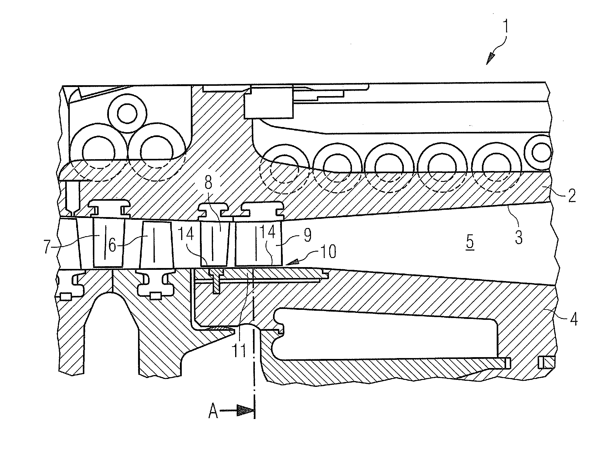
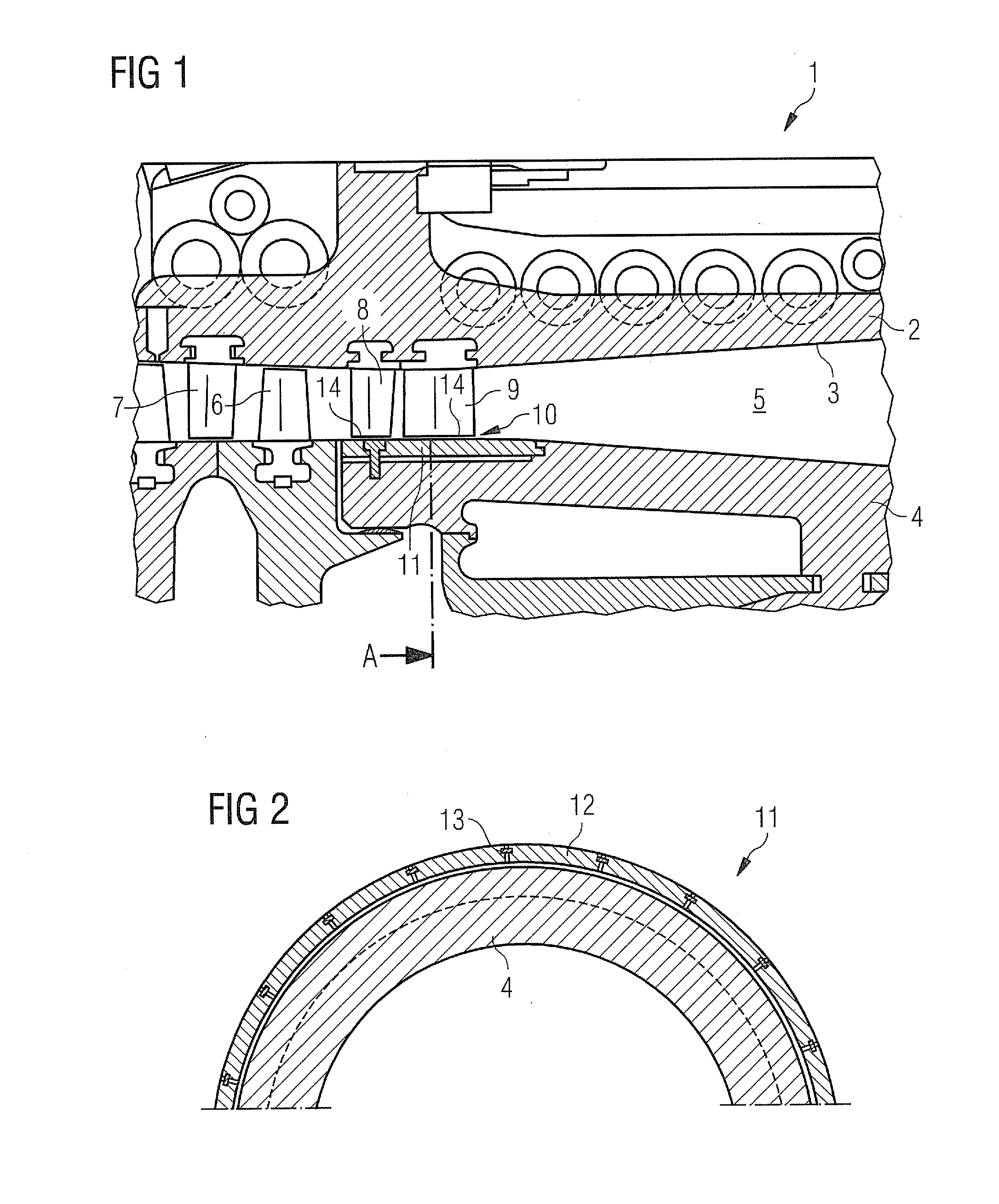
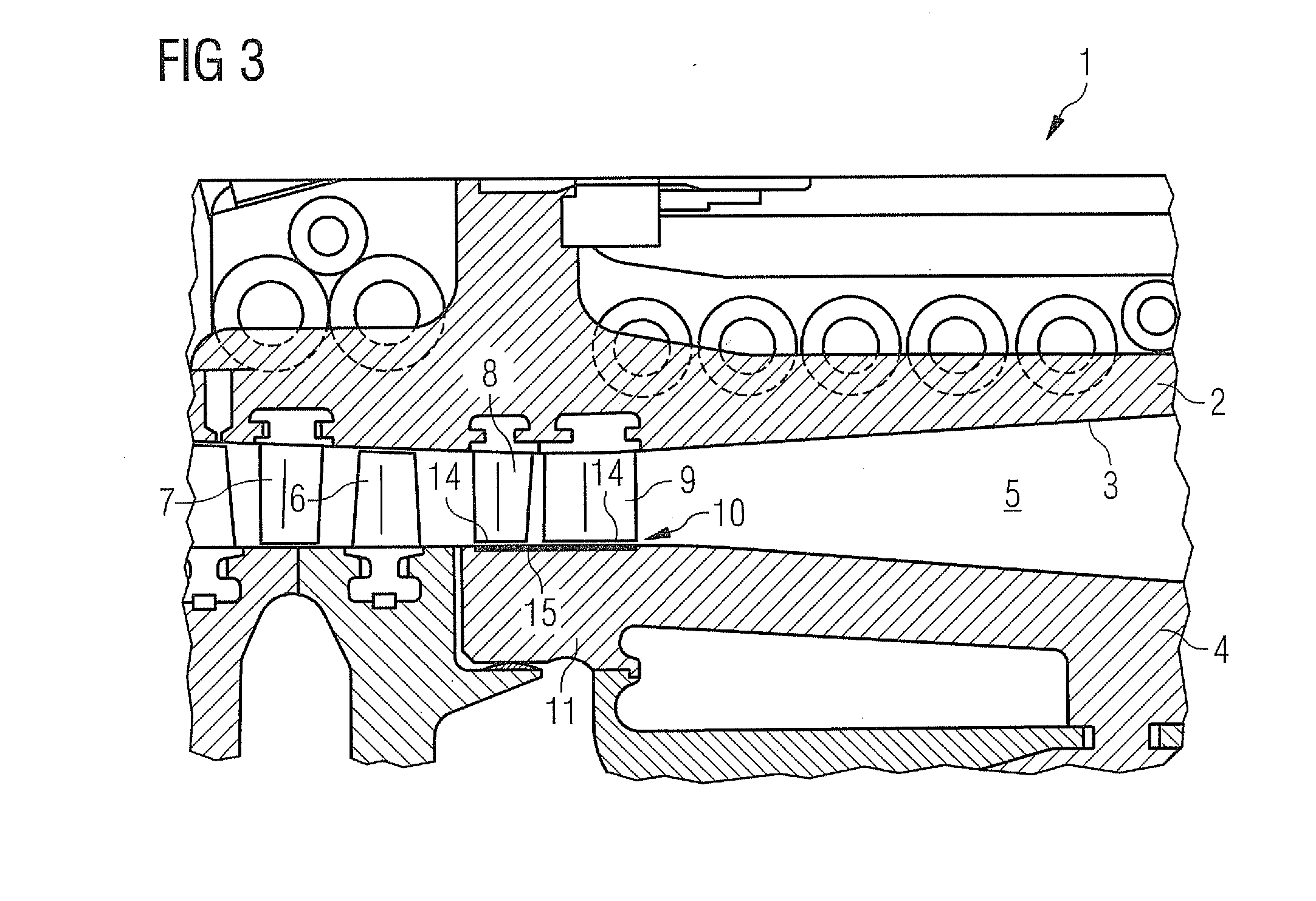
[0031]As is clear from FIG. 1, an axial compressor 1 has a casing 2 which has a casing contour 3 on its inside. Furthermore, the axial compressor 1 has a shaft (not shown) which is covered radially outwardly by a shaft cover 4. Both the shaft cover 4 and the casing contour 3 form a flow duct which is designed as a diffuser 5. Moreover, the axial compressor 1 has a rotor with rotor blading 6, the rotor being connected rigidly in terms of rotation to the shaft.

[0032]Stator blading 7 is provided, fastened to the casing 2, and is established upstream of the rotor blading 6. Downstream of the rotor blading 6 is arranged a guide vane cascade 8 and, downstream of this, a follow-up guide vane cascade 9, the guide vane cascade 8 and the follow-up guide vane cascade 9 forming the outflow region of the axial compressor 1. Both the guide vane cascade 8 and the follow-up guide vane cascade 9 are formed by a plurality of stator vanes which extend radially in the axial compressor 1. The stator van...


PUM


Abstract

An axial compressor for a gas turbine having passive radial gap control is provided. The axial compressor includes a guide vane support on which guide vanes are fastened so as to be arranged in a ring, wherein the vane tips of the guide vanes lie opposite a wall section. Thermal insulation is attached to the wall section in the section lying opposite the vane tips in order to equalize the expansion behavior of the guide vane support and the wall section, which by themselves react thermally in different manners, wherein the terminal insulation is matched in the heat input delay effect thereof to the wall section and to the guide vane support in such a way that the thermal expansion behavior of the guide vane support and the wall section is at least equalized over time during transient operation of the axial compressor.

Description

CROSS REFERENCE TO RELATED APPLICATIONS[0001]This application is the US National Stage of International Application No. PCT / EP2009 / 065359, filed Nov. 18, 2009 and claims the benefit thereof. The International Application claims the benefits of German application No. 08020995.0 EP filed Dec. 3, 2008. All of the applications are incorporated by reference herein in their entirety.FIELD OF INVENTION[0002]The invention relates to an axial compressor for a gas turbine having passive radial gap control, with at least one guide vane ring which is fastened to a guide vane carrier and has in each case a plurality of guide vanes, the vane tips of which lie on the hub side, in each case so as to form a radial gap, opposite a rotationally fixedly arranged wall portion reacting thermally more quickly in relation to the guide vane carrier.BACKGROUND OF INVENTION[0003]A gas turbine has a turbocompressor, for example, in an axial type of construction. The turbocompressor has a casing with stators at...

Claims


Application Information

Patent Timeline
Patent Type & Authority Applications(United States)
IPC IPC(8): F01D25/26
CPCF01D11/001F05D2300/50211F05D2300/5021F05D2230/90F01D11/005F01D11/025
Inventor BENKLER, FRANCOISKLEIN, KARLMATTHIAS, TORSTENSCHIRRMACHER, ACHIMSCHNEIDER, OLIVERSHEVCHENKO, VADIM
Owner SIEMENS AG
Why Eureka
Try Eureka