
Display apparatus and backlight unit

Inactive Publication Date: 2011-09-29
SAMSUNG ELECTRONICS CO LTD
View PDF3 Cites 6 Cited by
  • Summary
  • Abstract
  • Description
  • Claims
  • Application Information

AI Technical Summary

Benefits of technology

[0011]An aspect of an exemplary embodiment provides a display apparatus and a backlight unit which are capable of effectively achieving local dimming of the display apparatus.
[0012]An aspect of another exemplary embodiment provides a backlight unit using a local dimming method, which reduces inter-block interference and increases directivity of light, and a display apparatus using the same.
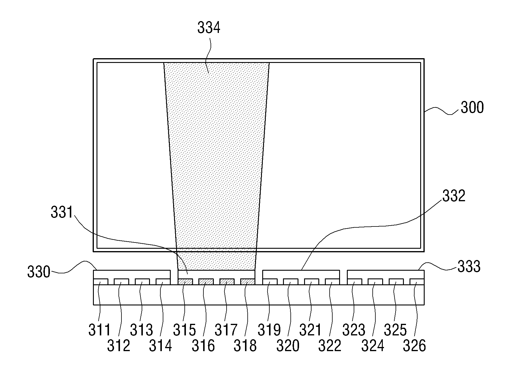
[0014]The light guide unit may be disposed toward the light guide plate such that the light projected onto the side surface of the light guide plate has increased directivity.
[0023]According to an aspect of another exemplary embodiment, a backlight unit includes: a light guide plate, a plurality of light sources which project light onto a side surface of the light guide plate, and a light guide unit disposed on at least one of the plurality of light sources, wherein the light guide unit increases the directivity of the light projected onto the side surface of the light guide plate.
[0024]The light guide unit is positioned relative to the light guide plate such that the light projected onto the side surface of the light guide plate has increased directivity.

Problems solved by technology

In particular, in a backlight unit adopting a local dimming method for providing backlight by controlling a light source on a block-by-block basis, inter-block interference may occur, making it difficult to achieve local dimming.
However, it is understood that the exemplary embodiments are not required to overcome the disadvantages described above, and the exemplary embodiments may not overcome any of the problems described above.

Method used


Image

  • Display apparatus and backlight unit
  • Display apparatus and backlight unit
  • Display apparatus and backlight unit

Examples


Embodiment Construction

[0043]Hereinafter, exemplary embodiments will be described in greater detail with reference to the accompanying drawings.

[0044]In the following description, same reference numerals are used for the same elements when they are depicted in different drawings. The matters defined in the description, such as detailed construction and elements, are provided to assist in a comprehensive understanding of the exemplary embodiments. Thus, it will be apparent that the exemplary embodiments can be carried out without those specifically defined matters. Also, functions or elements known in the related art are not described in detail since they would obscure the invention with unnecessary detail.

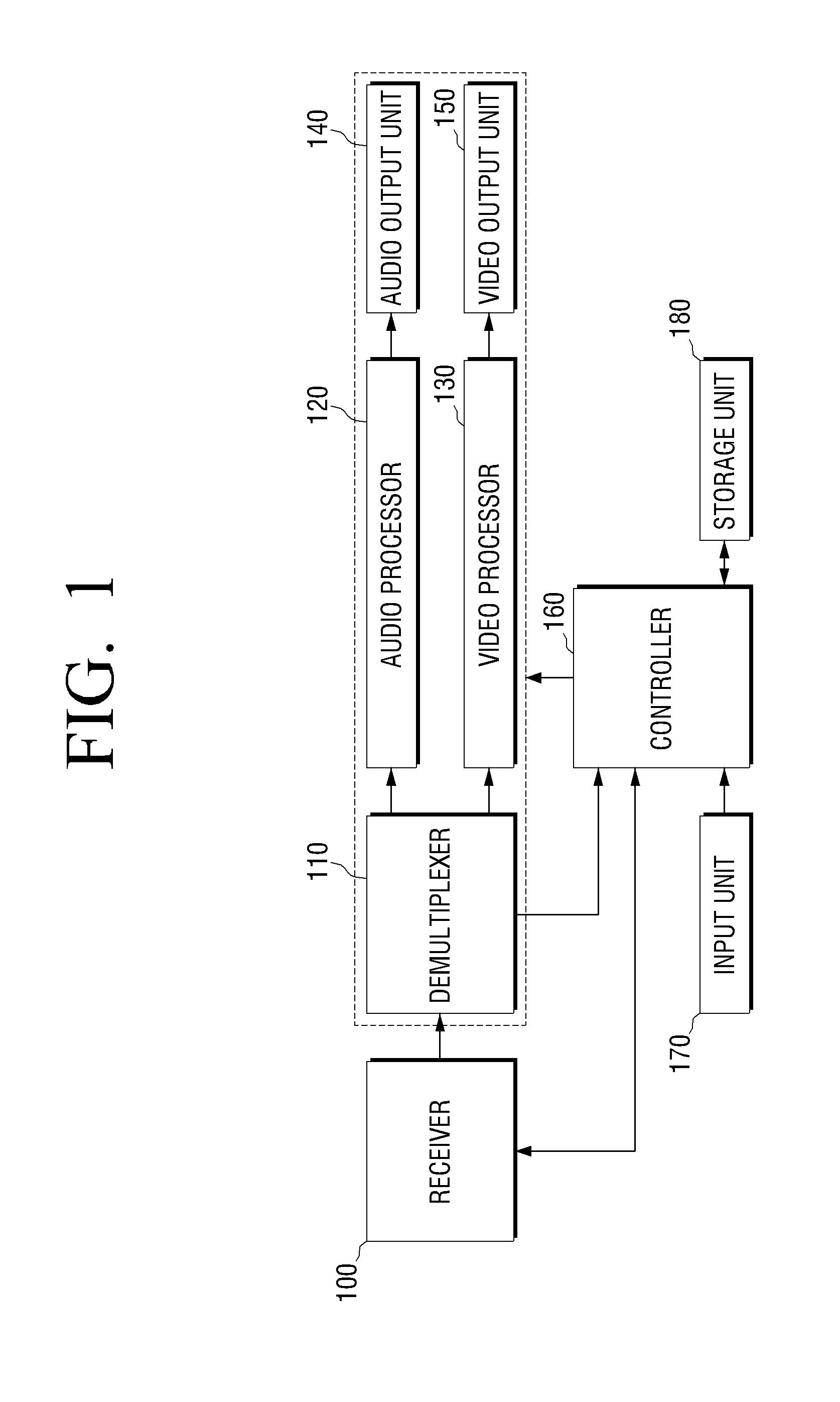
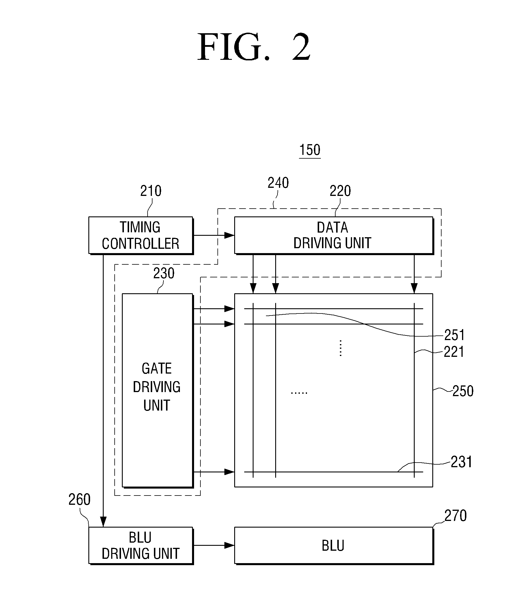
[0045]FIG. 1 is a block diagram illustrating a display apparatus according to an exemplary embodiment. The display apparatus according to an exemplary embodiment includes a receiver 100, a demultiplexer 110, an audio processor 120, a video processor 130, an audio output unit 140, a video output unit 150,...


PUM


Abstract

A display apparatus and a backlight unit for lighting the display apparatus are provided. The backlight unit includes a light guide plate, a plurality of light sources which project light onto a side surface of the light guide plate, and a light guide unit which is provided in each of at least two groups of light sources. The light guide unit is disposed toward the light guide plate in order to limit diffusion of a path of the light projected onto the side surface of the light guide plate. Accordingly, the light enters the light guide plate in a narrow path in a direction that is perpendicular to the side wall of the light guide plate, so that local dimming is achieved effectively.

Description

CROSS-REFERENCE TO RELATED APPLICATION[0001]This application claims priority from Korean Patent Application No. 10-2010-0027862, filed on Mar. 29, 2010, in the Korean Intellectual Property Office, the disclosure of which is incorporated herein by reference in its entirety.BACKGROUND[0002]1. Field[0003]Apparatuses and methods relate generally to a display apparatus and a backlight unit, and more particularly, to a display apparatus which increases directivity of light to provide effective backlight and a backlight unit thereof.[0004]2. Description of the Related Art[0005]With the development of multimedia apparatuses such as the television, mobile phone, and laptop computer, the demand for the development of technologies in the field of flat panel display devices relating to display apparatuses is growing. A representative flat panel display device may be a plasma display panel (PDP), a liquid crystal display (LCD), a field emission display (FED), and a vacuum fluorescent display (VF...

Claims


Application Information

Patent Timeline
IPC IPC(8): G02F1/1335F21V7/22H05B37/02
CPCG02B6/0021G02B6/0073G02B6/0068G02B6/0028
Inventor JEONG, KYUNG-OCK
Owner SAMSUNG ELECTRONICS CO LTD
Learn More