
Monitor for automobile

a monitor and automobile technology, applied in the field of monitors, can solve the problems of increasing the possibility of accidents, affecting the safety of driving, and the visual angle is usually too limited to allow safe driving, and the monitors are more complicated and expensiv

Inactive Publication Date: 2011-09-29
HON HAI PRECISION IND CO LTD
View PDF4 Cites 0 Cited by
  • Summary
  • Abstract
  • Description
  • Claims
  • Application Information

AI Technical Summary

Benefits of technology

The system provides a simple, cost-effective solution for expanding the driver's visual field to 180 degrees behind the vehicle, enhancing safety by continuously displaying panoramic images without noticeable image changes, thus reducing the risk of accidents during reversing.

Problems solved by technology

Because the monitor is secured in the automobile, this visual angle is usually too limited to allow for the safe driving of the automobile.
For example, when the automobile is reversing, a driver can only see objects in a range covering a visual angle of about 30 degrees to left and right in which the automobile is reversing, thus increasing the possibility of an accident.
Monitors provided with a visual angle of more than 60 degrees can be used to extend the visual field of the driver, but these monitors require expensive optical components such as components with high refractive index or low dispersive power, thus these monitors tend to be more complicated and more expensive.

Method used


Image

  • Monitor for automobile
  • Monitor for automobile
  • Monitor for automobile

Examples


first embodiment

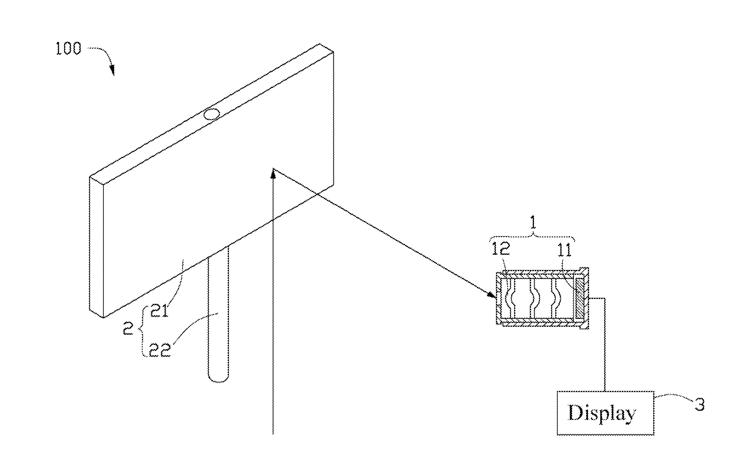
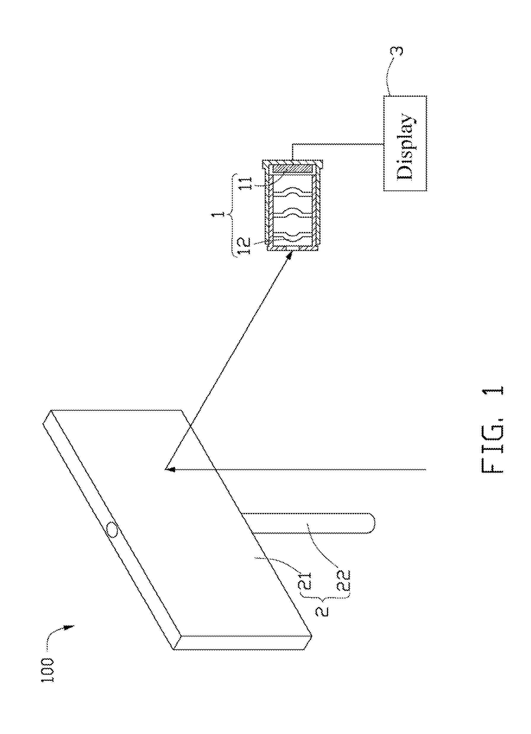
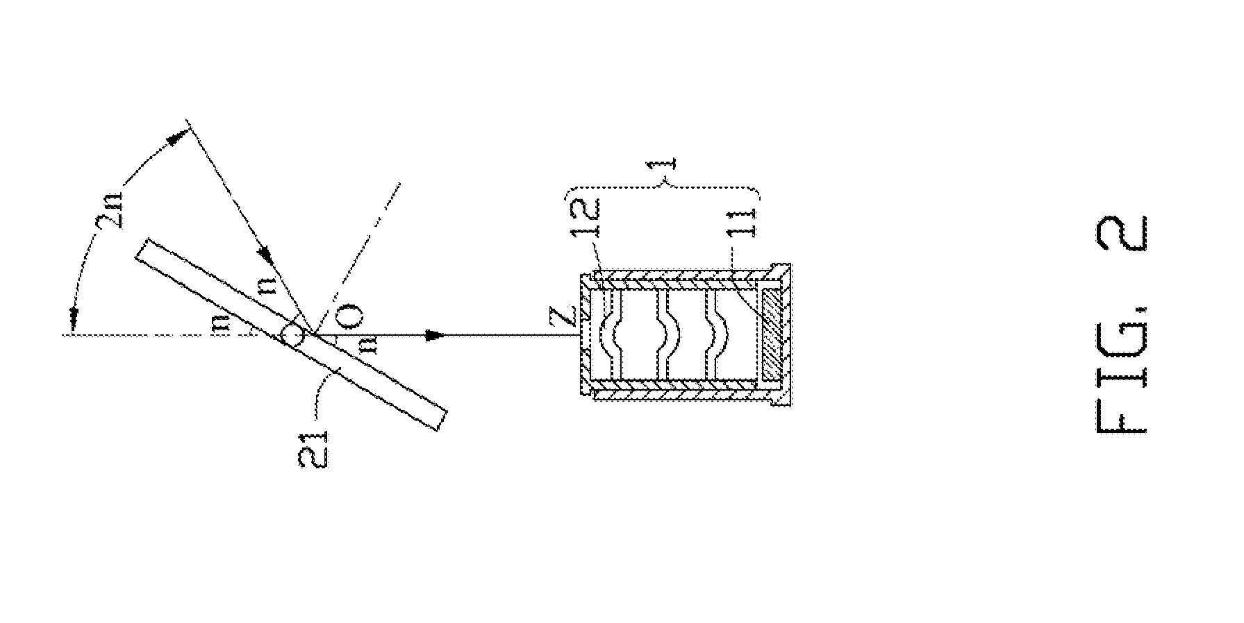
[0013]Referring now to the drawings, FIG. 1 shows a monitor 100 used in an automobile (not shown) according to the present disclosure. Additionally, the monitor 100 can be used in other vehicles and also in fixed installations. The monitor 100 includes an image sensing module 10, a visual field adjustor 20 and a display 30. The image sensing module 10 is installed in the automobile for receiving optical image signals. An optical axis of the image sensing module 10 points to the rear of the automobile. The visual field adjustor 20 is installed on an incident light path of the image sensing module 10 to adjust the visual field of the monitor 100. The display 30 is electronically connected with the image sensing module 10 and is mounted to the automobile for processing and displaying image signals received by the image sensing module 10 to a driver of the automobile.

[0014]The image sensing module 10 includes an image sensor 11 and a lens module 12. The image sensor 11 is a charge coupl...

second embodiment

[0019]Referring FIG. 4 and FIG. 5, a monitor 200 is provided. All components of the monitor 200 are similar to the monitor 100 except that a prism 41 replaces the mirror 21 of the monitor 100. The prism 41 is movably installed in the incident light path of the lens module 12. The prism 41 is made from transparent materials such as glass and includes a trapeziform bottom (not labeled), a first side 411, a second side 412, a third side 413 and a fourth side 414. The first side 411 is parallel to the second side 412 and the area of the first side 411 is larger than the area of the second side 412. The third side 413 and the fourth side 414 both intersect with the first side 411 and the second side 412. The third side 413 and the fourth side 414 both form an angle of 60 degrees to the first side 411. Two reflectors (not shown) are respectively installed on the third side 413 and the fourth side 414. The second side 412 is located between the first side 411 and the lens module 12. The p...


PUM


Abstract

A monitor used in an automobile includes an image sensing module, a visual field adjustor, and a display. The image sensing module includes a lens module and an image sensor secured on an emitting light path of the lens module. The visual field adjustor includes a prism made from transparent materials and movably installed in an incident light path of the lens module. When the automobile reverses, the image sensing module cooperates with the visual field adjustor to capture optical image signals, and the display uses the optical image signals to create an image and displays the image.

Description

CROSS-REFERENCE TO RELATED APPLICATION[0001]This application is a divisional application of U.S. Ser. No. 11 / 309, 259, filed on Jul. 20, 2006.BACKGROUND[0002]1. Technical Field[0003]The present disclosure generally relates to monitors, and more particularly relates to a monitor that has a large visual field.[0004]2. Description of Related Art[0005]Nowadays automobiles are often provided with a monitor secured in the tail end to cover the blind spots of their rearview mirrors. Generally, the visual angle of the monitor is designed to be about 60 degrees. Because the monitor is secured in the automobile, this visual angle is usually too limited to allow for the safe driving of the automobile. For example, when the automobile is reversing, a driver can only see objects in a range covering a visual angle of about 30 degrees to left and right in which the automobile is reversing, thus increasing the possibility of an accident. Monitors provided with a visual angle of more than 60 degrees...

Claims


Application Information

Patent Timeline
Patent Type & Authority Applications(United States)
IPC IPC(8): H04N7/18
CPCB60R1/00H04N7/183H04N5/2259B60R2300/101H04N23/58B60R1/28B60R1/26
Inventor LEE, CHUN-YU
Owner HON HAI PRECISION IND CO LTD
Learn More