
Vehicle side body structure

Active Publication Date: 2011-09-29
HONDA MOTOR CO LTD
View PDF8 Cites 77 Cited by
  • Summary
  • Abstract
  • Description
  • Claims
  • Application Information

AI Technical Summary

Benefits of technology

[0010]In view of the foregoing prior art problems, it is an object of the present invention to provide an improved vehicle side body structure which uses a high-tensile steel plate for forming the outer side panel unit and can thereby reduce the number of inner reinforcements to achieve a reduced weight of the outer side panel unit, and which not only can achieve an improved outer appearance by reducing the gap between the roof rail section and the door but also can sufficiently bear a lateral collision load and efficiently disperse the lateral collision load.
[0011]It is another object of the present invention to provide an improved vehicle side body structure which can eliminate a need for a great press forming load, prevent occurrence of a crack etc. in the center pillar section and retain quality stability.
[0012]It is still another object of the present invention to provide an improved vehicle side body structure which not only allows the center pillar section of the outer side panel unit to be formed of a high-strength steel plate, but also has a reduced weight and increased strength.

Problems solved by technology

However, if such a high-tensile steel plate is used for forming the roof rail section of the outer side panel unit disclosed in the relevant patent literature, small bends cannot be formed by press forming.
Thus, the technique disclosed in the relevant patent literature cannot achieve an improved outer appearance by reducing a gap between the roof rail section and a door.
Even when a high-tensile steel plate is used for forming the center pillar section, the center pillar section merely overlaps the roof rail section, and thus, a lateral collision cannot be dispersed efficiently.
However, the center pillar section is of a shape requiring deep drawing work, and thus, if a steel plate of a tensile strength equal to or greater than 590 MPa is used for forming the center pillar section, then there may undesirably occur cracks in the center pillar section during press forming.
However, if a high-tensile steel plate is used for forming the center frame (outer center pillar section), there may undesirably occur cracks in corners of the center frame (outer center pillar section) after plastic forming of the center frame.

Method used


Image

  • Vehicle side body structure
  • Vehicle side body structure
  • Vehicle side body structure

Examples


Embodiment Construction

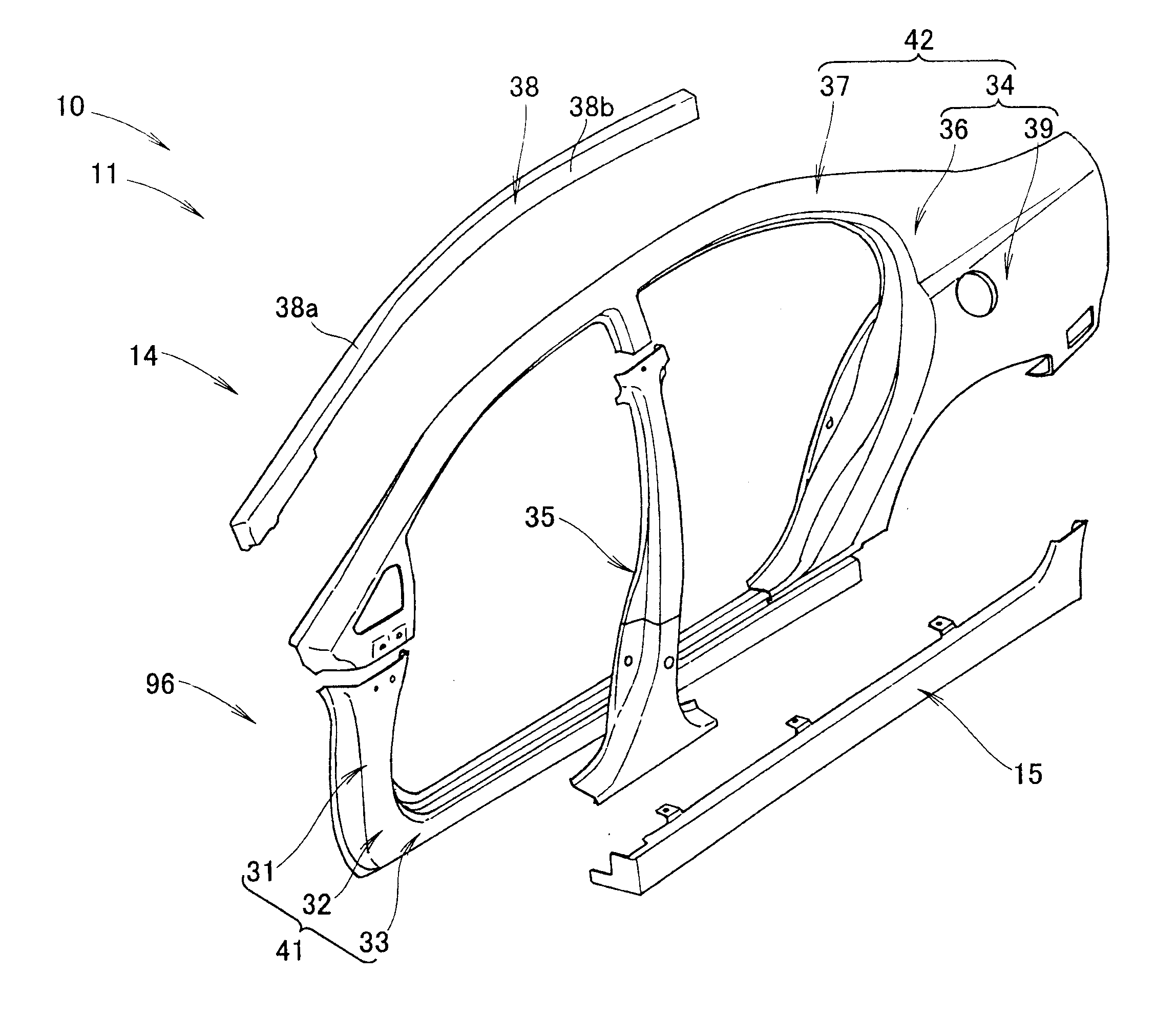
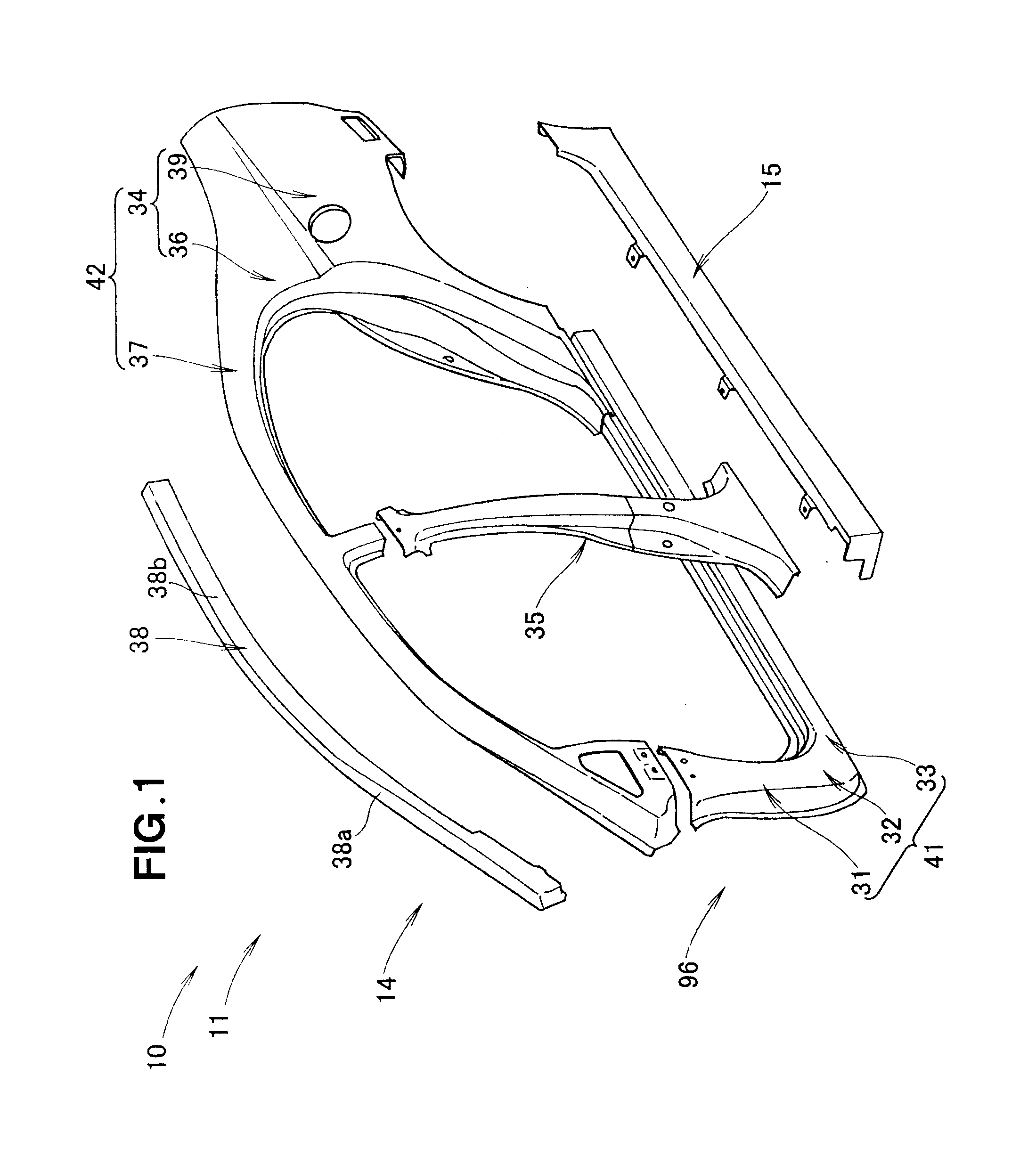
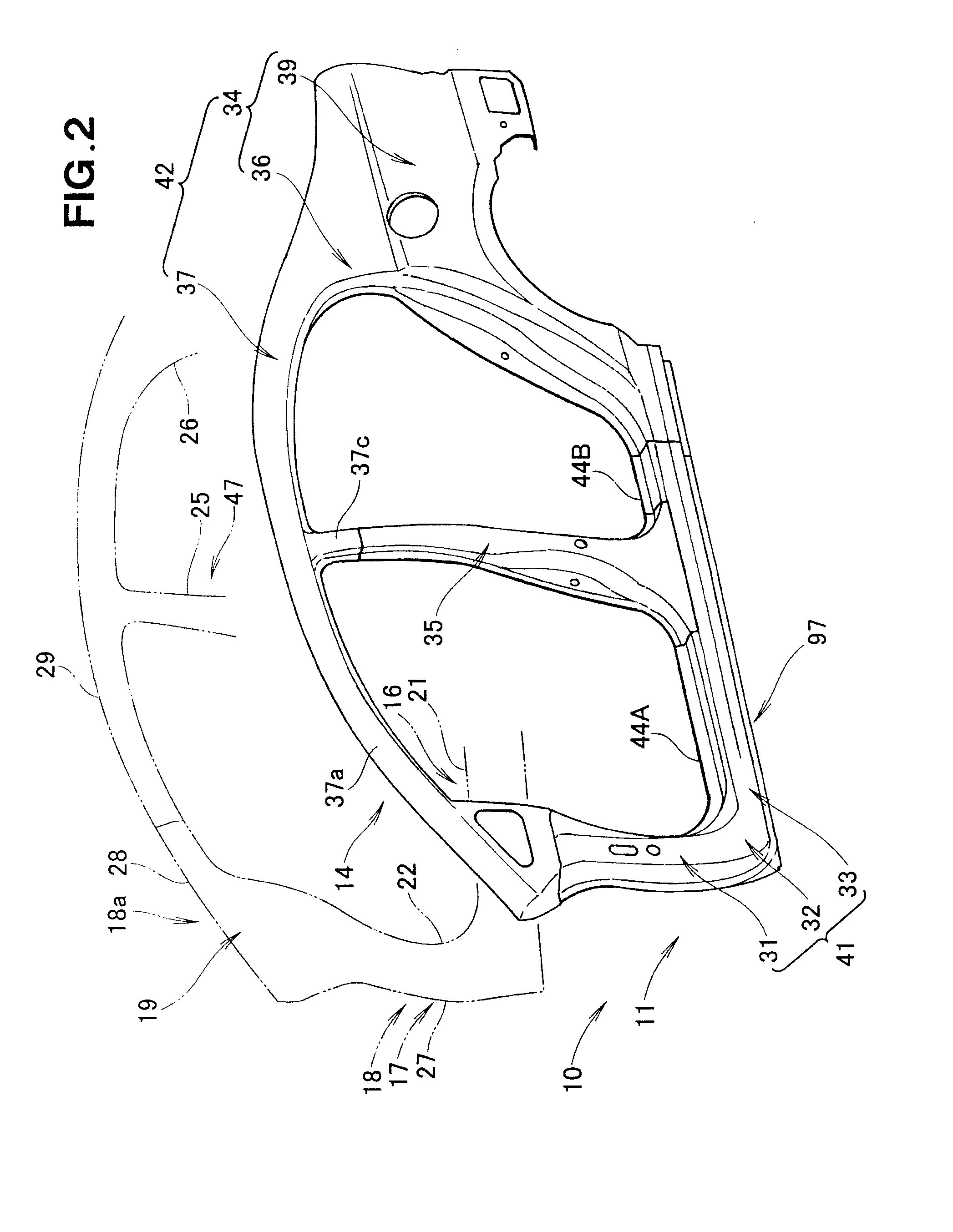
[0066]As shown in FIGS. 1 to 4, an embodiment of a vehicle side body structure 10 of the present invention includes an outer side panel unit 14 to which are fixedly joined various members and which covers a side surface of an inner side panel unit 19 of a vehicle body 11, and a side sill garnish 15 that covers an outer side sill section 33 of the outer side panel unit 14 from outside.

[0067]The outer side panel unit 14 is fixedly joined to the inner side panel unit 19 in such a manner as to form a closed section between the outer side panel unit 14 and the inner side panel unit 19. The inner side panel unit 19 includes an inner side sill section 21, an inner front pillar section 27 (including a inner lower front pillar section 22), an inner center pillar section 25 and an inner rear pillar section 26.

[0068]The outer side panel unit 14 includes: the outer side sill section 33 that covers the inner side sill section 21 from outside the vehicle body 11; a lower portion 31 of the outer f...


PUM


Abstract

A center pillar section formed of a high-tensile steel plate is fixed to a side panel frame section including a roof rail section formed of an ordinary-tensile steel plate. A reinforcing member formed of a high-tensile steel plate is provided inside the roof rail section, and the center pillar section is fixed at its upper end portion to the outer surface of the reinforcing member and at its lower end portion to the side sill section. A door beam provided within a front door overlaps the center pillar section and lower portion of a front pillar section. Front and rear end portions of the door beam are opposed to respective increased-width portions of the front pillar section and center pillar section.

Description

FIELD OF THE INVENTION[0001]The present invention relates generally to vehicle side body structures which includes an outer side panel unit that covers a side of a vehicle body from outside.BACKGROUND OF THE INVENTION[0002]Generally, in vehicle side body structures, a roof rail section, a slanting front pillar section, a lower front pillar section, a side sill section and a center pillar section are formed of plates (or plate materials), such as cold rolled steel plates, and these plates are sequentially fixedly joined together to construct an outer side panel unit. Namely, first, the roof rail section, slanting front pillar section, lower front pillar section and side sill section are fixedly joined together, and then, the center pillar section is fixedly joined to the thus joined-together roof rail section, slanting front pillar section, lower front pillar section and side sill.[0003]With such vehicle side body structures, where all of the plates except for one plate are first fix...

Claims


Application Information

Patent Timeline
IPC IPC(8): B62D25/02
CPCB62D25/02B62D29/007B62D25/04B62D25/025
Inventor NAGAI, SHIGEYUKITANAKA, TOMOHISATAKAYAMA, YUSUKEMIZOHATA, HITOSHIWATANABE, YASUNORI
Owner HONDA MOTOR CO LTD
Learn More