
LED street lamp

Inactive Publication Date: 2011-09-29
SET
View PDF12 Cites 53 Cited by
  • Summary
  • Abstract
  • Description
  • Claims
  • Application Information

AI Technical Summary

Benefits of technology

In order to overcome the above-mentioned shortcomings, the present invention provides a light emitting diode (LED) street lamp, and more particularly, to an LED street lamp using an LED as a light source and capable of minimizing a luminance deviation within an illuminated area while extending the illuminated area and increasing the entire luminance of the illuminated area.
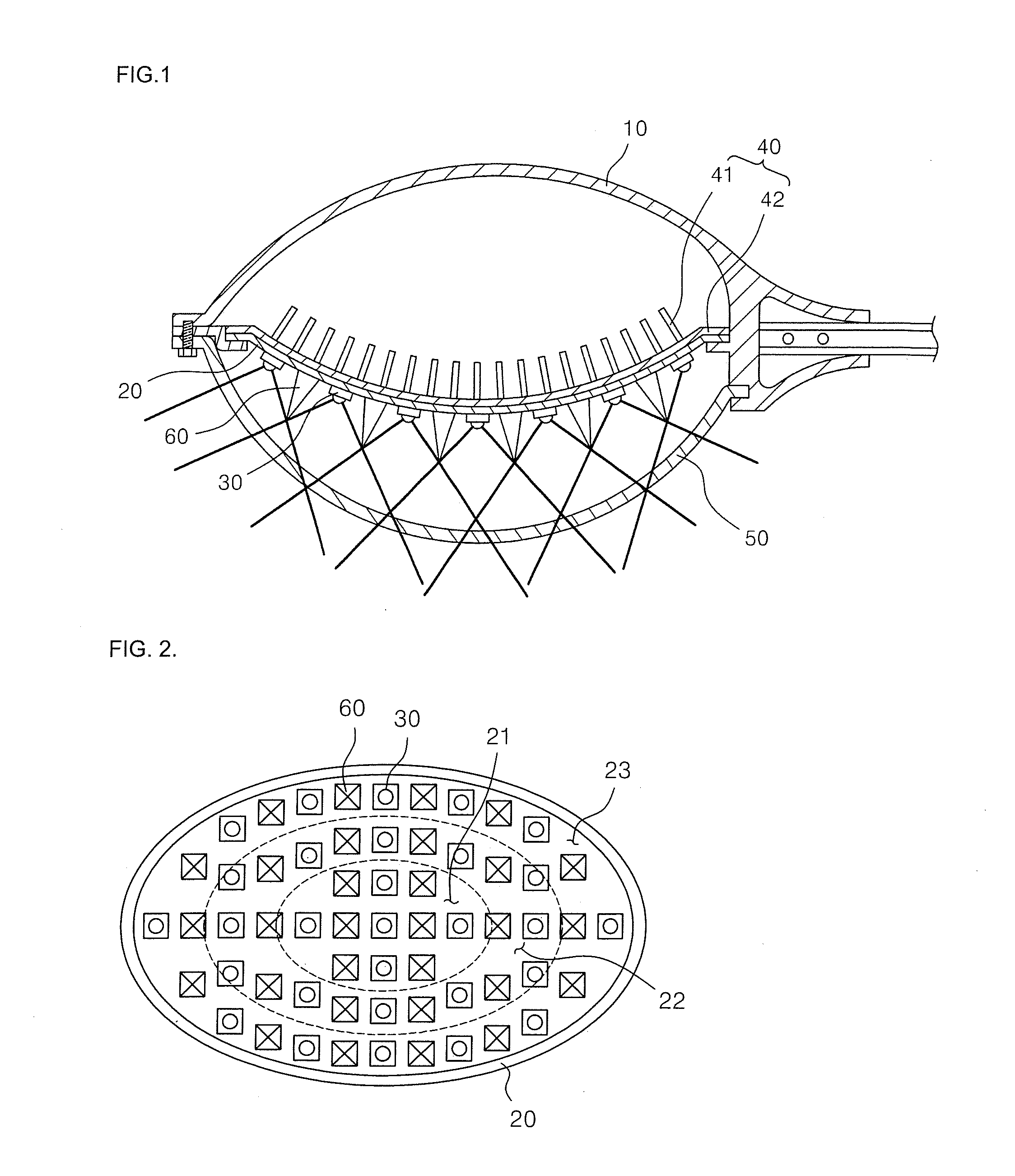
As described above, in the LED street lamp according to the present invention, a plurality of LEDs having different luminance levels are arranged on a convex or concave surface of a board, the plurality of LEDs being arranged such that the luminance gradually increases from the center to the edge of the surface, thereby enlarging an illuminated area while preventing the overall luminance of the illuminated area from decreasing.
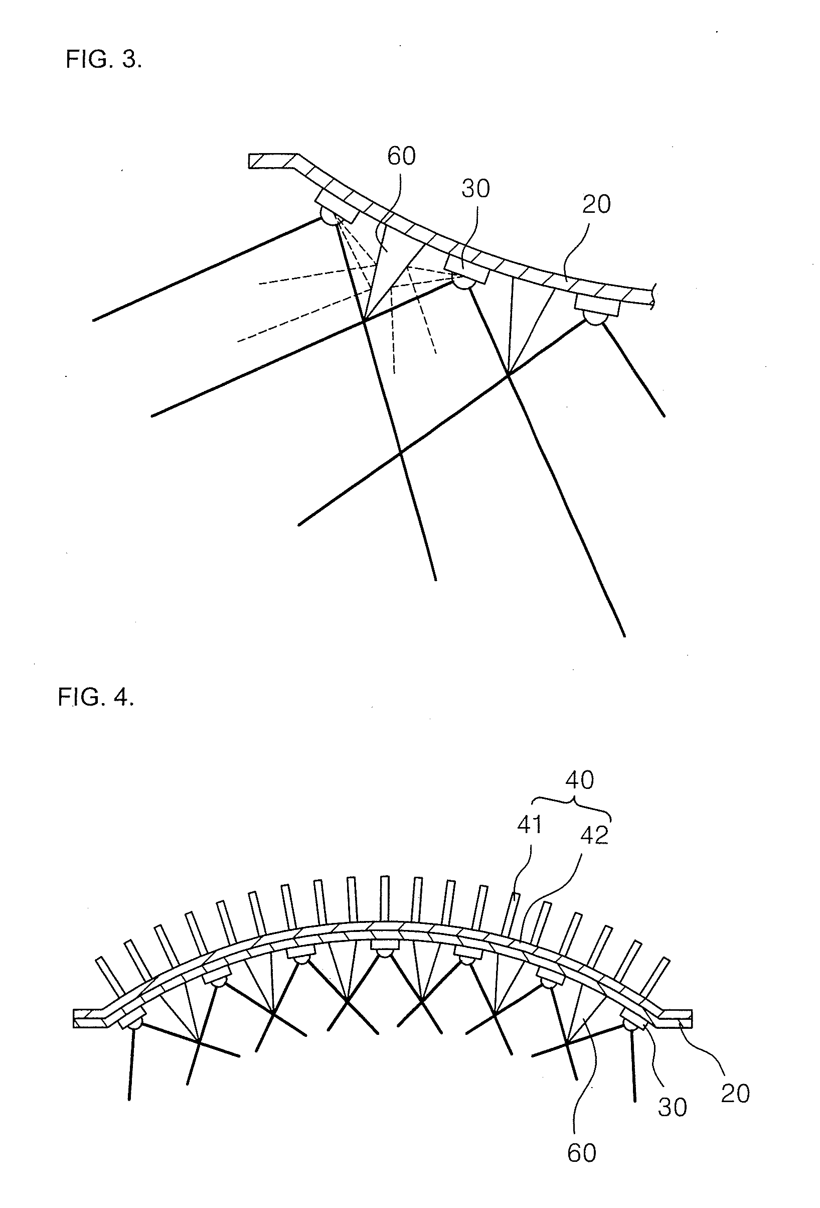
In addition, some of light emitted the LEDs may be diffused between two neighboring ones of the plurality of LEDs by a diffusing member, thereby increasing the luminance of the illuminated area, and prevent a blind zone between adjacent street lamps by enlarging the illuminated area without sacrificing the luminance.
Further, in a case where the LEDs have the same luminance, they are arranged such that a beam angle between two adjacent LEDs decreases gradually from the central portion to the edge of the board, thereby preventing the luminance from decreasing while enlarging the illuminated area

Problems solved by technology

The electric lamp usually employs a bulb, shortening the service life of the electric lamp and lowering impact resistance.
However, since the conventional LED lamp includes a plurality of LEDs arranged on the aluminum board of a flat panel type, a high intensity of luminance cannot be illuminated to an area between adjacent street lamps, producing a blind zone.

Method used


Image

  • LED street lamp
  • LED street lamp
  • LED street lamp

Examples


Embodiment Construction

Hereinafter, embodiments of the present invention will be described in detail with reference to the accompanying drawings.

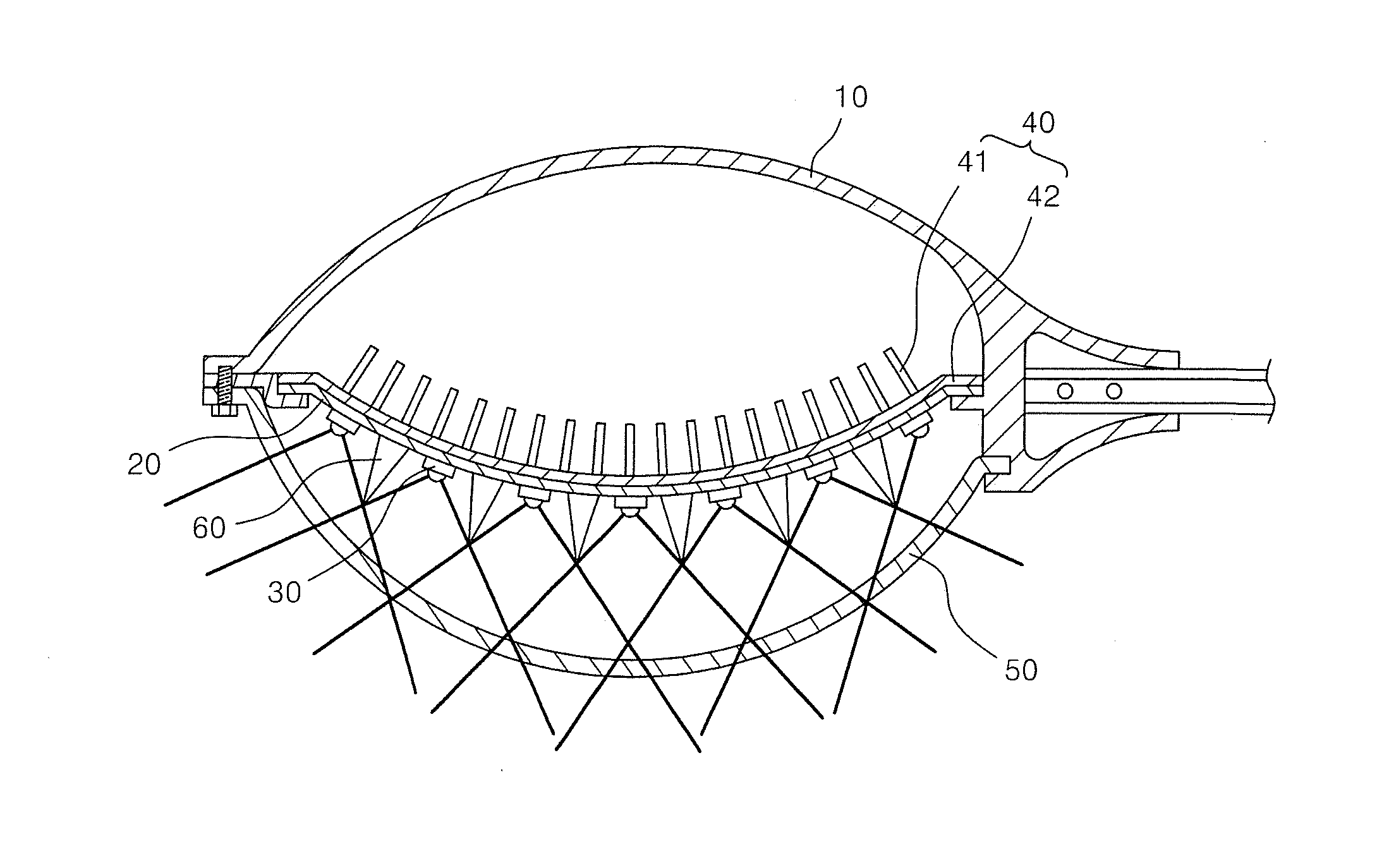
FIG. 1 illustrates an LED street lamp according to an embodiment of the present invention, and FIG. 2 illustrates LEDs and diffusing members arranged on a board of the LED street lamp shown in FIG. 1.

Referring to FIGS. 1 and 2, the LED street lamp according to the illustrated embodiment includes a case 10 provided at a front end of a post, a board 20 provided within the case 10 and having a plurality of LEDs 30 mounted thereon, and heat dissipating units 40 dissipating heat generated when the LEDs 30 emit light.

The case 10 has a space in which the board 20 and the heat dissipation units 40 are mounted, and an opening formed on one side surface thereof. The cover 50 made of glass or a transparent resin material to allow the light emitted from the LEDs to be transmitted, is coupled to the opening.

The board 20 is convexly formed, and the LEDs 30 are arranged on the ...


PUM


Abstract

Disclosed is a light emitting diode (LED) street lamp using an LED as a light source and capable of minimizing a luminance deviation within an illuminated area while increasing the luminance of the entire illuminated area. The LED street lamp includes a case provided at a front end of a lamp post; a board provided inside the case and having a plurality of LEDs spaced apart from each other; and heat dissipation units closely adhered to the board and dissipating heat generated when the LEDs emit light, wherein the plurality of LEDs have different luminance levels from each other, the luminance levels gradually increase from the center of the board to the edge of the board, and diffusing members diffusing the light generated from the plurality of LEDs are provided on board portions corresponding to areas between each of the plurality of LEDs.

Description

CROSS-REFERENCE TO RELATED APPLICATIONThis application claims priority to and the benefit of Korean Patent Application No. 10-2008-0129052, filed on Dec. 18, 2008, the entire content of which is incorporated herein by reference.BACKGROUND OF THE INVENTION1. Field of the InventionThe present invention relates to a light emitting diode (LED) street lamp, and more particularly, to an LED street lamp using an LED as a light source and capable of minimizing a luminance deviation within an illuminated area while increasing the luminance of the entire illuminated area.2. Description of the Related ArtIn general, a street lamp is an illumination device installed along a road for ensuring the safety and security of a road traffic. The street lamp includes a lamp post fixed on a ground surface along a road, and a street lamp head integrally formed at an end of the lamp post to be directed toward the road. An electric lamp is provided within the street lamp head to emit light, thereby illumina...

Claims


Application Information

Patent Timeline
IPC IPC(8): H01L33/64
CPCF21S8/086F21W2131/103F21Y2111/004Y02B20/72F21Y2111/002F21Y2101/02F21Y2113/00F21Y2115/10F21Y2107/10F21Y2107/20F21V29/89F21V29/74F21S13/10
Inventor AN, HAENG SUKIM, JUNG SUK
Owner SET
Learn More