
Air Filter Element

a filter element and air technology, applied in the field of air filter elements, can solve the problems of difficult to provide a filter element with both a considerable pleat height and element width, and the pleats tend to collapse, so as to improve filtration performance, reduce manufacturing costs, and increase surface area

Inactive Publication Date: 2011-09-29
MANN HUMMEL GMBH
View PDF2 Cites 14 Cited by
  • Summary
  • Abstract
  • Description
  • Claims
  • Application Information

AI Technical Summary

Benefits of technology

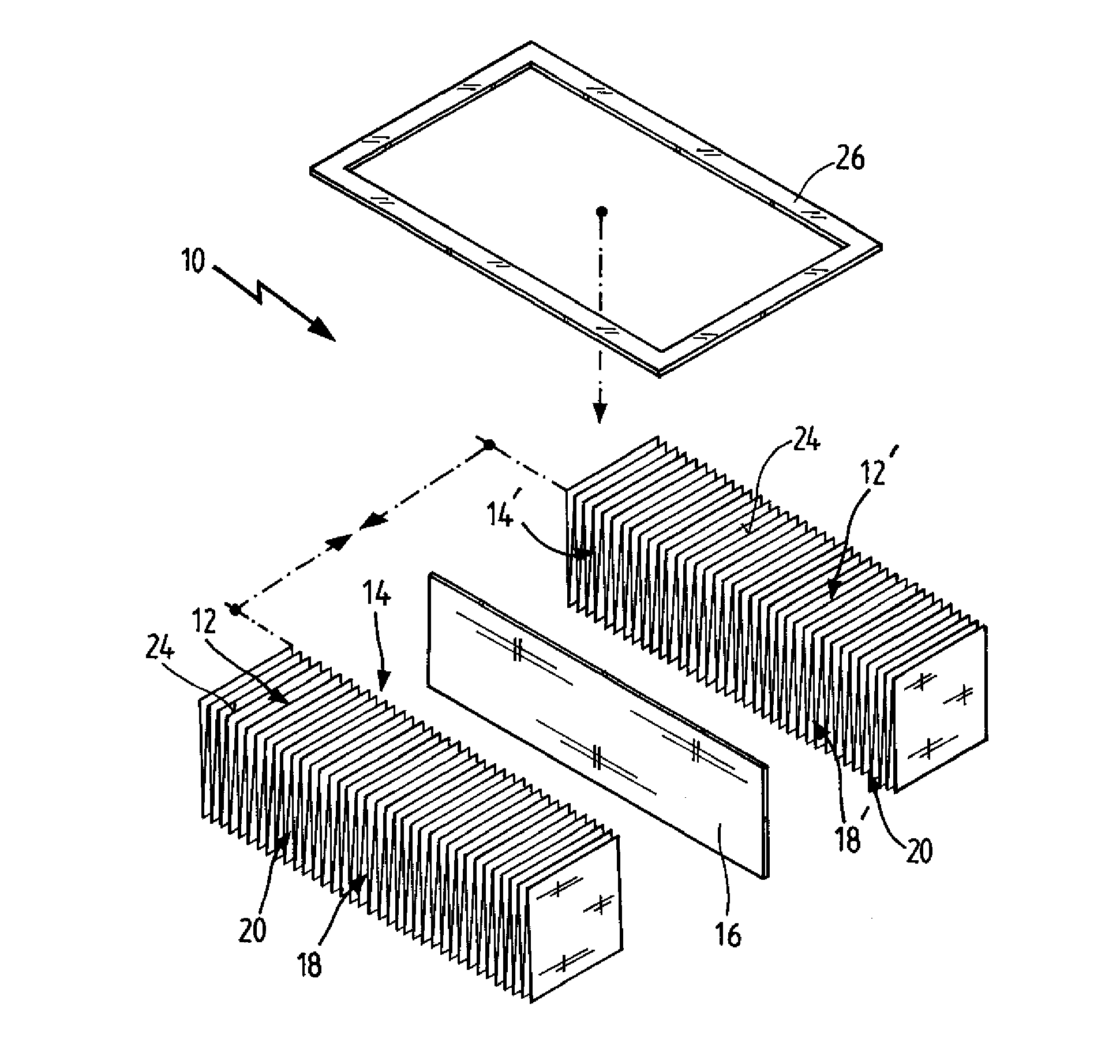
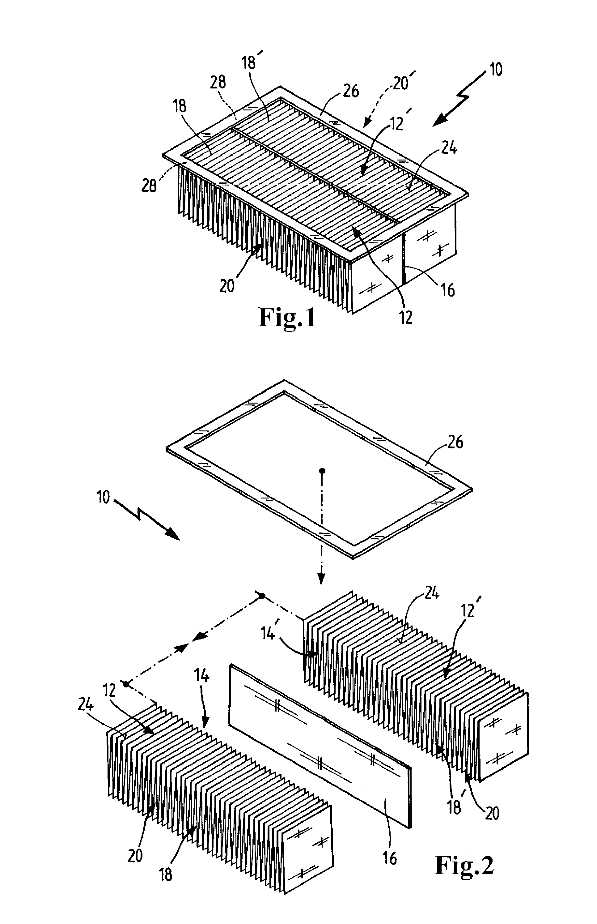
The present invention provides an air filter element with a substantially planar configuration and comprising at least two pleated filter media that are arranged side by side and attached to each other in a permanent way by a connecting member connecting facing longitudinal edges of the filter media. This design solves the problem of pleat instability in conventional filter elements and allows for new filter layouts and improved filtration performance. The connecting member may comprise at least one material strip, preferably of fibrous, in particular of non-woven material, which simplifies an exact alignment of the pleated filter media and thus the assembly of the filter element. The pleated filter media is preferably made from a non-woven, particularly synthetic, fibrous material. The invention also provides a sealed fit of the filter element in a respective filter casing, which allows for a tight fit and prevents leakage.

Problems solved by technology

In practical applications, a filter element is usually placed in a filter casing, which, especially in mobile vehicles, offers very limited space.
However, when increasing the pleat height, pleat stability may be a problem when a certain pleat height is exceeded, the stability of the pleats depending also on the width of the filter element, i.e. on the length of the folding edges of the pleats.
In other words, it is difficult to provide a filter element with has both a considerable pleat height and element width, as in such filter elements, the pleats tend to collapse due to their own weight and / or due to the flux of the gaseous medium that needs to be filtered.
Thus, the passage for the medium to be filtered may become at least partially obstructed, increasing overall flow resistance and thereby decreasing efficiency of the filter element.
As the stability of the pleats depends on the stiffness of the material of the filter medium used, this problem is particularly relevant when using filter media having a comparatively low stiffness, such as non-woven filter media.

Method used


Image

  • Air Filter Element
  • Air Filter Element

Examples


Embodiment Construction

[0020]Before describing in detail embodiments that are in accordance with the present invention, it should be observed that the embodiments reside primarily in combinations of apparatus components related to an air filter element. Accordingly, the apparatus components have been represented where appropriate by conventional symbols in the drawings, showing only those specific details that are pertinent to understanding the embodiments of the present invention so as not to obscure the disclosure with details that will be readily apparent to those of ordinary skill in the art having the benefit of the description herein.

[0021]In this document, relational terms such as first and second, top and bottom, and the like may be used solely to distinguish one entity or action from another entity or action without necessarily requiring or implying any actual such relationship or order between such entities or actions. The terms “comprises,”“comprising,” or any other variation thereof, are inten...


PUM

PropertyMeasurementUnit
resistanceaaaaaaaaaa
mechanical wearaaaaaaaaaa
sizeaaaaaaaaaa

Abstract

An air filter element (10) has a substantially planar configuration and comprises at least two pleated filter media (12, 12′), said pleated filter media (12, 12′) being arranged side by side and attached to each other in a permanent way by a connecting member (16) connecting facing longitudinal edges (14, 14′) of said filter media (12, 12′).

Description

CROSS REFERENCE TO RELATED APPLICATIONS[0001]This application claims the benefit under 35 USC 119 of European Patent Application 10290156.8 filed on Mar. 24, 2010, and which is hereby incorporated by reference in its entirety.TECHNICAL FIELD[0002]The invention relates to an air filter element, having a substantially planar configuration.BACKGROUND OF THE INVENTION[0003]Filter elements of this kind generally serve for filtration of gaseous media and are widely used as particulate air filters for removal of solid particulates such as dust, pollen etc. They may e.g. be placed in the outside air intake of a vehicles passenger compartment or may be used as combustion air filters to prevent abrasive particulate matter from entering an engine's cylinders, where the particulate matter would cause mechanical wear and possibly damage.[0004]In practical applications, a filter element is usually placed in a filter casing, which, especially in mobile vehicles, offers very limited space. The effi...

Claims


Application Information

Patent Timeline
Patent Type & Authority Applications(United States)
IPC IPC(8): B01D46/52
CPCB01D46/002B01D46/521B01D46/12B01D46/58
Inventor CHAMPION, ARNAUDNABUCET, GURVAN
Owner MANN HUMMEL GMBH
Learn More