
Multi-Projector Display System Calibration

a multi-projector display and display system technology, applied in the field of multi-projector display systems, can solve problems such as saving processing time, and achieve the effect of saving processing tim

Active Publication Date: 2011-09-22
SEIKO EPSON CORP
View PDF11 Cites 43 Cited by
  • Summary
  • Abstract
  • Description
  • Claims
  • Application Information

AI Technical Summary

Benefits of technology

[0012]In a prior embodiment of the present invention, a first Gray code technique and a second raster calibration technique are combined to create a precise mapping between pixel locations of the camera and pixel locations of the projector(s). In a present, first embodiment of the invention the technique of using the raster calibration images is eliminated by interpolating the projector coordinate information decoded from the Gray code images. This saves processing time.
[0013]While certain techniques of the present invention work well for displaying video or still images, text requires even more precision. In a second embodiment of the invention, camera images are processed to reduce errors caused by noise so that text can be displayed without any noticeable misalignment between projectors.

Problems solved by technology

This saves processing time.

Method used


Image

  • Multi-Projector Display System Calibration
  • Multi-Projector Display System Calibration
  • Multi-Projector Display System Calibration

Examples


Embodiment Construction

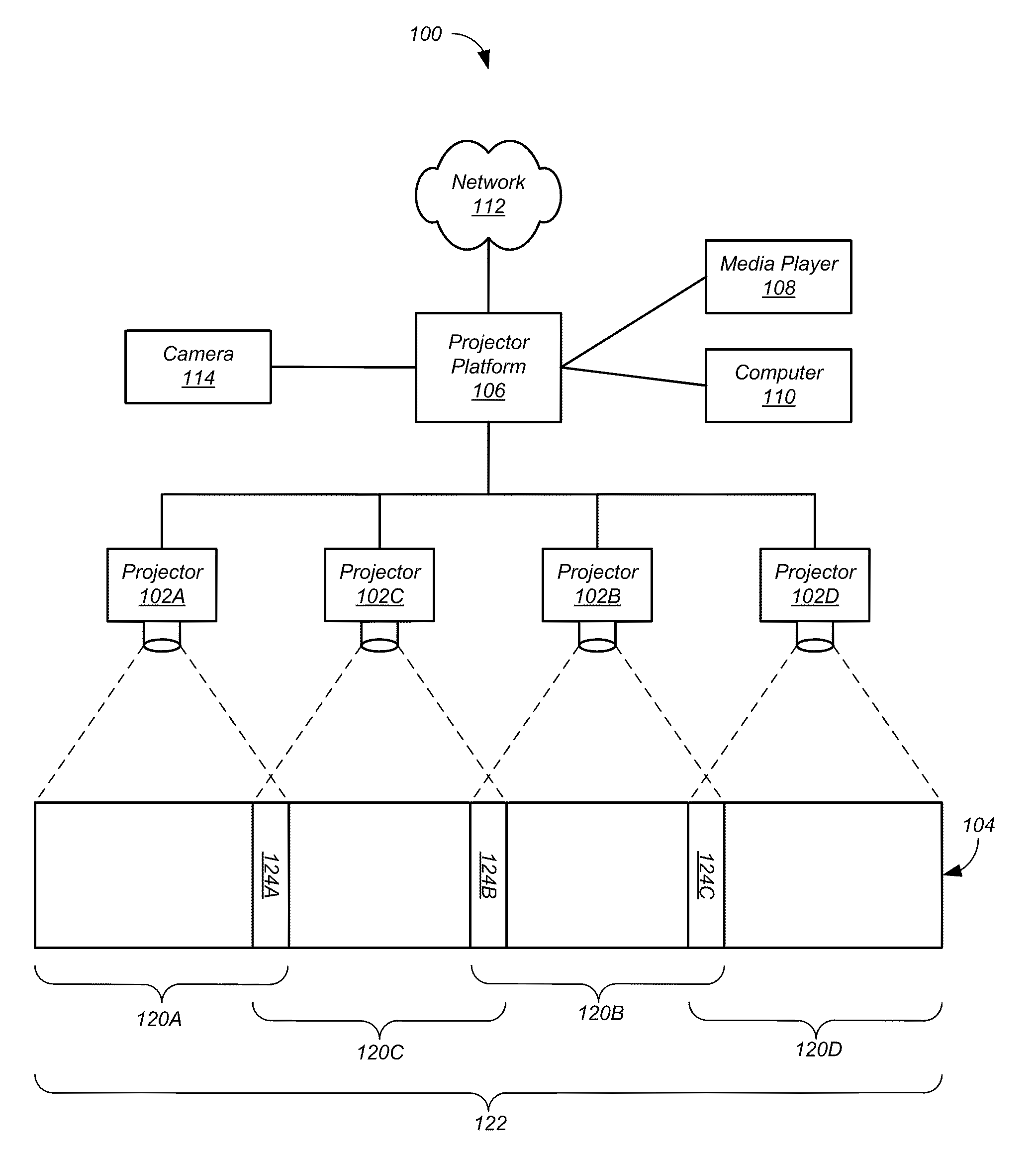
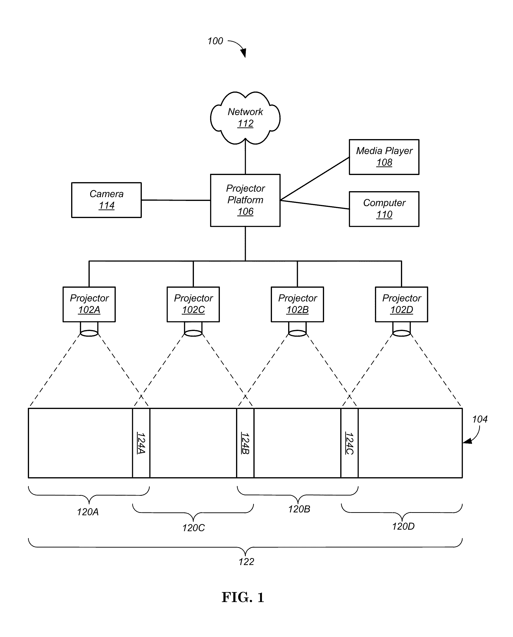
[0065]The present invention relates to camera-based registration of projector display systems. During registration, one or more projectors project calibration images upon a display surface. A camera captures one or more images of each projected calibration image. A projector platform creates a mapping, for each projector, between pixel locations of the camera and pixel locations of the projector. After registration, the mappings are used to alter the images prior to projection so that seamless composite image can be displayed by the multiple projectors.

[0066]These mappings are stored in Virtual Pixel Map (VPM) files that form an accurate pixel registration map of each projector. Using the VPM files, each physical device pixel on a projector can be mapped to one or more logical pixels in a virtual region defining the large format display (composite image). This virtual large format display resolution defines the unit of each VPM pixel, which is a virtual pixel in the logical display ...


PUM


Abstract

A first Gray code technique and a second raster calibration technique can be combined to create a precise mapping between pixel locations of the camera and pixel locations of the projector(s). In one aspect the technique of using the raster calibration images is eliminated by interpolating the projector coordinate information decoded from the Gray code images. In another aspect camera images are processed to reduce errors caused by noise so that text can be displayed without any noticeable misalignment between projectors. In a third aspect, a scale factor is calculated based on the relative height / width of projector regions in the captured calibration images. Calibration images are recalculated using the scale factor to provide greater correspondence between the mapping of a low resolution camera to the high-resolution projectors.

Description

CROSS-REFERENCE TO RELATED APPLICATIONS[0001]This application is related to commonly assigned U.S. patent application Ser. No. 12 / 549,011, filed Aug. 27, 2009, which is hereby incorporated by reference in its entirety.BACKGROUND[0002]1. Field of Invention[0003]The present invention relates generally to multi-projector display systems. More particularly, the present invention relates to accurate calibration of the system during registration of the each of the multiple projectors.[0004]2. Background[0005]With an ever growing desire to see more information with better quality, large-screen displays have become quite popular. Increasing screen resolutions and sizes are continually emerging and made available in televisions, computer monitors, and other video devices. Until recently, large screen displays were typically too costly, physically unwieldy, or simply unavailable. Video projectors provided one solution, enabling a wide range of communication and entertainment functions by offe...

Claims


Application Information

Patent Timeline
Patent Type & Authority Applications(United States)
IPC IPC(8): H04N17/00
CPCH04N9/3147H04N9/3182H04N17/00H04N9/3194H04N9/3185
Inventor NELSON, STEVE
Owner SEIKO EPSON CORP
Learn More