
Car parking administration system

a technology for parking administration and parking meters, applied in the direction of instruments, transportation and packaging, apparatus for dispensing discrete objects, etc., can solve the problems of relatively scarce distribution network for charging stations of this type at present, and the operating range is still relatively small, so as to increase the mobility of electric vehicles, buy parking time, and buy energy.

Inactive Publication Date: 2011-09-22
WOLFIEN PATRICK
View PDF9 Cites 39 Cited by
  • Summary
  • Abstract
  • Description
  • Claims
  • Application Information

AI Technical Summary

Benefits of technology

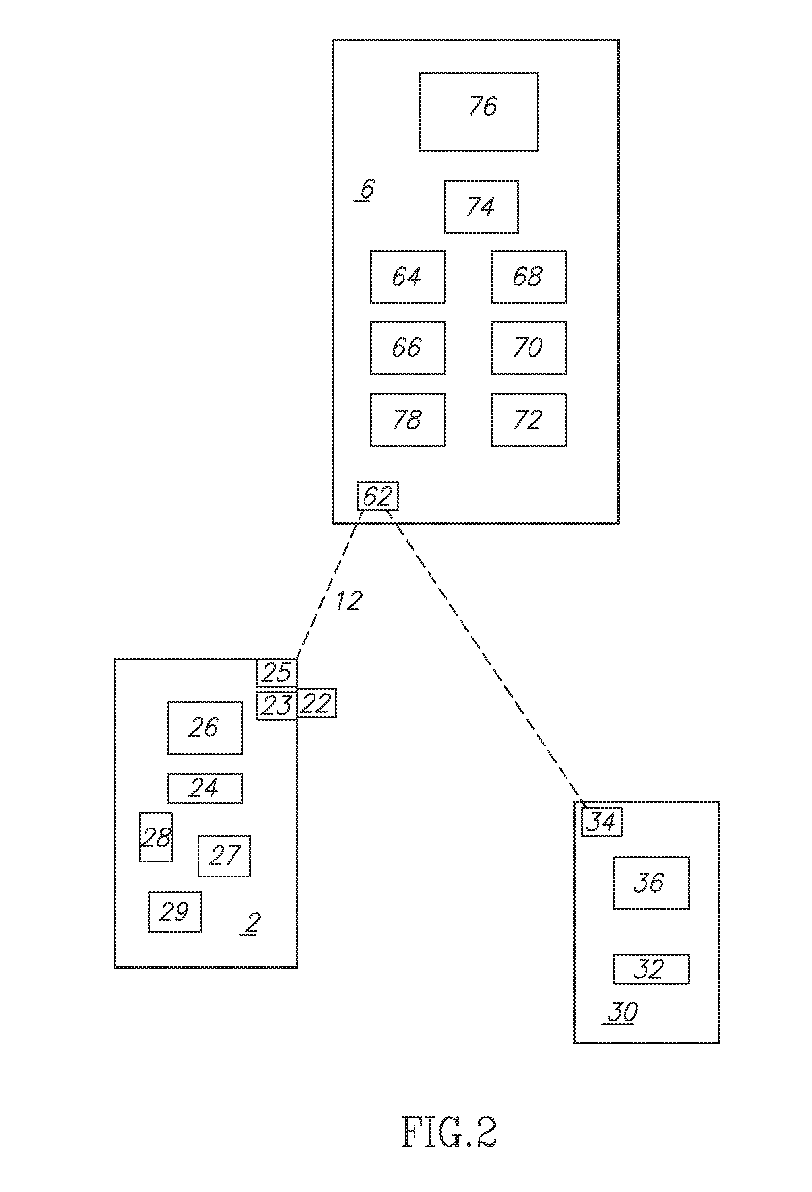
[0004]The present invention is directed to increasing the mobility of electric vehicles. A car parking system according to the invention for charging motor vehicles with electrical energy has at least one charging station which is capable of being coupled electrically to a motor vehicle in order to charge a charge storage unit of this motor vehicle. In this case this charging station has associated with it at least one parking space for temporarily parking the vehicle to be charged. According to the invention the car parking system has at least one central processing unit which is preferably separate from the charging station and which communicates in terms of data with the charging station, wherein data characteristic of the motor vehicle are capable of being transferred by way of a communication link existing at least temporarily between the central processing unit and the charging station. It is therefore proposed according to the invention to provide a car parking system with a function which will allow it to charge the batteries of electrically driven vehicles. In this way, in addition to buying parking time, it will also be possible to buy energy for charging the vehicles.
[0008]An embodiment of the car parking system includes a plurality of charging stations which communicate with the central processing unit. In this case it may be possible for the number of the charging stations to be altered in the course of enlargements, in which case, however, more or fewer charging stations of this type can be connected to the same central processing unit. With this solution it will be possible to make allowance for the growth in the market for electrically operated vehicles and also for the corresponding follow-up investments. If for example the number of users or of necessary attachment points increases, then the follow-up costs are relatively low. It is advantageous for the charging station to be attached to a current distribution network, and this allows the supply of electrical energy to the vehicles.
[0010]In yet an alternative embodiment, the charging station has an electrical connection means in order to produce an electrical cable-supported connection to a motor vehicle. In this case it is possible for this connection means to be connected to corresponding standardized electrical attachment points of the vehicle. In this way for example a connection to an underside of the vehicle would be possible. In addition, it would be possible for the connection means to be connected automatically to the vehicle when the vehicle is parked and for the user for example only to have to park the vehicle at a pre-determined position. It is preferable for the charging station to be controlled by the central processing unit with which in particular it communicates. In addition, the system can have locking mechanisms which are arranged for example at the individual charging stations and which prevent unauthorized use of the electrical connection means.
[0016]In yet an alternative embodiment, the charging station allows different types of current supply. In this way, for example, both 230 V / 16 A normal charging and 400 V / 32 A rapid charging are possible.
[0017]In an alternative embodiment, a charging station can also have an alarm device which for example displays faulty operation, destruction and the like. In addition, the charging station can also have a recognition device for the motor vehicle, such as allow for example recognition by means of RFID chips and the like. In this way it is possible for the customer to have the possibility either of having his or her vehicle charged or of only carrying out a parking procedure.

Problems solved by technology

A problem with using electrically operated vehicles of this type has long been that their operating range is still relatively small, so that they have to be regularly re-charged with electric current.
The distribution network for charging stations of this type is still relatively scarce at present.

Method used


Image

  • Car parking administration system
  • Car parking administration system
  • Car parking administration system

Examples


Embodiment Construction

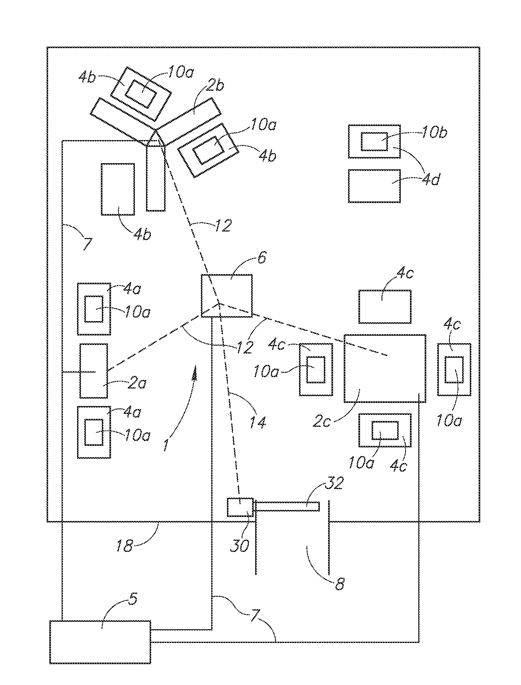
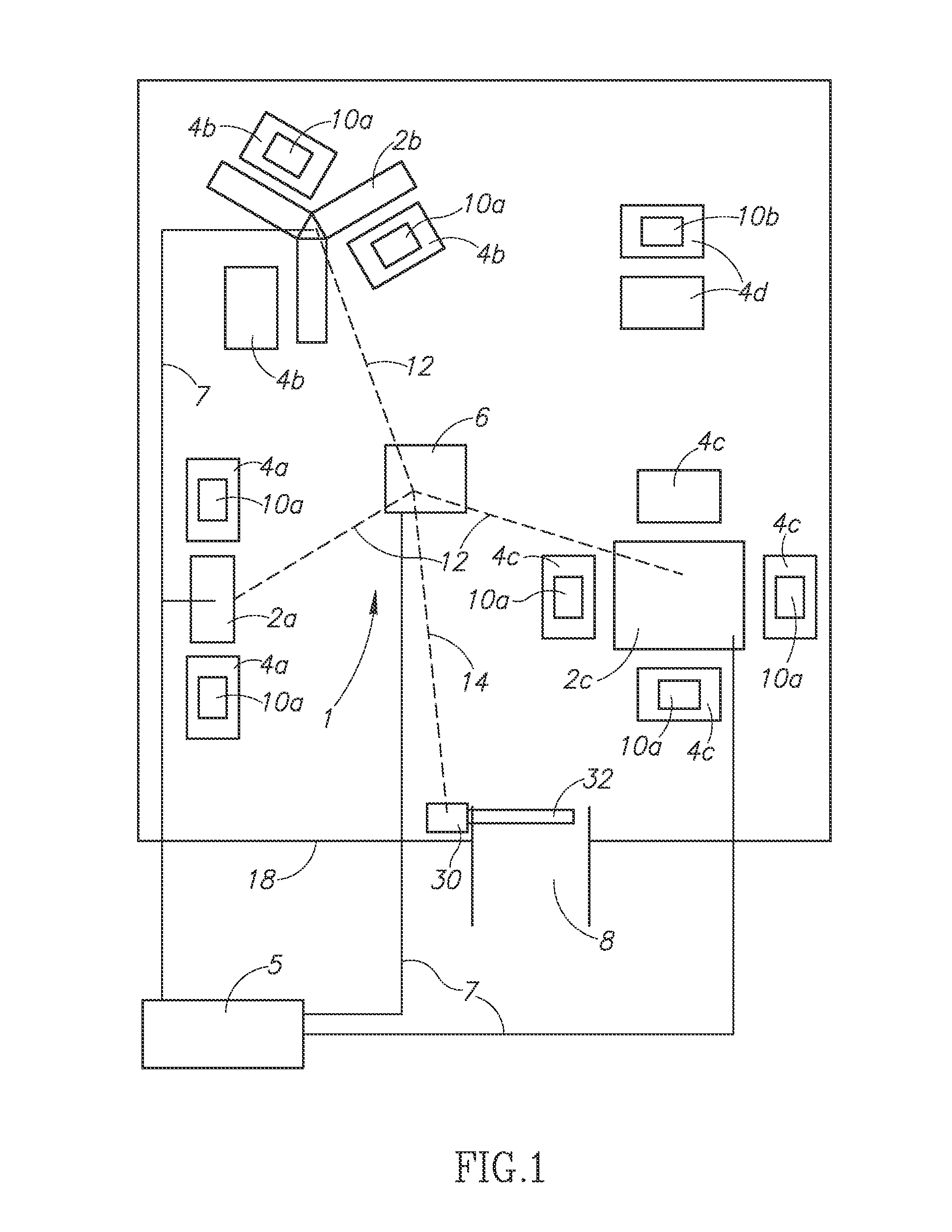
[0034]FIG. 1 is a diagrammatic illustration of a car parking system 1 according to the invention. In this case this car parking system 1 has three charging stations 2a, 2b, 2c, two parking spaces 4a being associated with charging station 2a, three parking spaces 4b being associated with charging station 2b and four parking spaces 4c being associated with charging station 2c. The number of the parking spaces, however, which are allocated to each charging station 2 in each case, can be varied. Motor vehicles 10a are present on some of the aforesaid parking spaces 4a, 4b, 4c. In addition, further parking spaces 4d are provided which, however, are not allocated to a charging station 2 and which are thus suitable for conventional cars 10b, for example.

[0035]The car parking system 1 has an energy supply unit 5, such as for example a public energy distribution network, by way of which the individual charging stations 2 are supplied with electrical energy by way of connecting lines 7. In th...


PUM


Abstract

A car parking system for charging motor vehicles with electrical energy, with at least one charging station which is capable of being coupled electrically to a motor vehicle in order to charge a charge storage unit of this motor vehicle, wherein this charging station has associated with it at least one parking space for temporarily parking the motor vehicle to be charged. According to the invention the car parking system has at least one central processing unit which is separate from the charging station and which communicates in terms of data with the charging station, wherein data characteristic of the motor vehicle are capable of being transferred by way of a communication link existing at least temporarily between the central processing unit and the charging station.

Description

PRIORITY CLAIM[0001]This application claims the benefit of German Application Serial No. 10 2010 012 366.8-31 filed Mar. 22, 2010, contents of which are incorporated herein.FIELD OF THE INVENTION[0002]The present invention relates to a car parking administration system.BACKGROUND OF THE INVENTION[0003]Car parking administration systems have long been known from the prior art. In this case it is possible for example to control, by way of a controlled access with a barrier, access to a car park, in order to be able to calculate subsequently, on leaving the car park, a specified fee which usually depends upon the time spent parked. During this parking time the vehicles usually stand on the parking spaces allocated to them. In recent years efforts have been made to increase the environmental compatibility of vehicles. In the context of this development, electric vehicles are also becoming more popular, which also have electric motors in addition to or instead of engines operated by liqu...

Claims


Application Information

Patent Timeline
Patent Type & Authority Applications(United States)
IPC IPC(8): H02J7/00
CPCB60L11/1816G07F15/003G07F15/005G07F17/24Y02T10/7005Y02T90/125Y02T90/128Y02T90/14Y02T90/16B60L11/1827Y02T90/121Y02T10/7072B60L53/14B60L53/35B60L53/665B60L2240/70B60L2250/30G08G1/14G08G1/146Y04S30/14G07F9/002Y02T10/72Y02T10/70Y02T90/12Y02T90/167
Inventor WOLFIEN, GERHARD
Owner WOLFIEN PATRICK
Learn More