
Pneumatic tire

a technology of pneumatic tires and cylinders, applied in the field of pneumatic tires, can solve the problems of inability to consider satisfactory and inability to form a layer, and achieve the effect of high water pickup effect and high braking ability on i

Inactive Publication Date: 2011-09-15
YOKOHAMA RUBBER CO LTD
View PDF13 Cites 8 Cited by
  • Summary
  • Abstract
  • Description
  • Claims
  • Application Information

AI Technical Summary

Benefits of technology

[0010]In light of the foregoing problems, the present technology provides a studless pneumatic tire that displays a high water pickup effect and edge effect when traveling on icy and snowy road surfaces at initial use, and after initial use also displays high braking ability on ice and steering stability on snow when traveling on icy and snowy road surfaces.
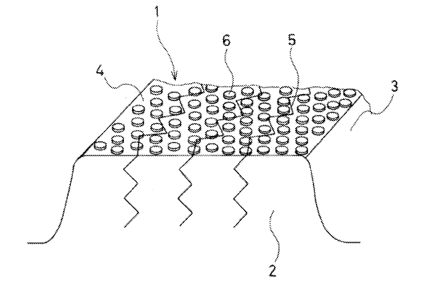
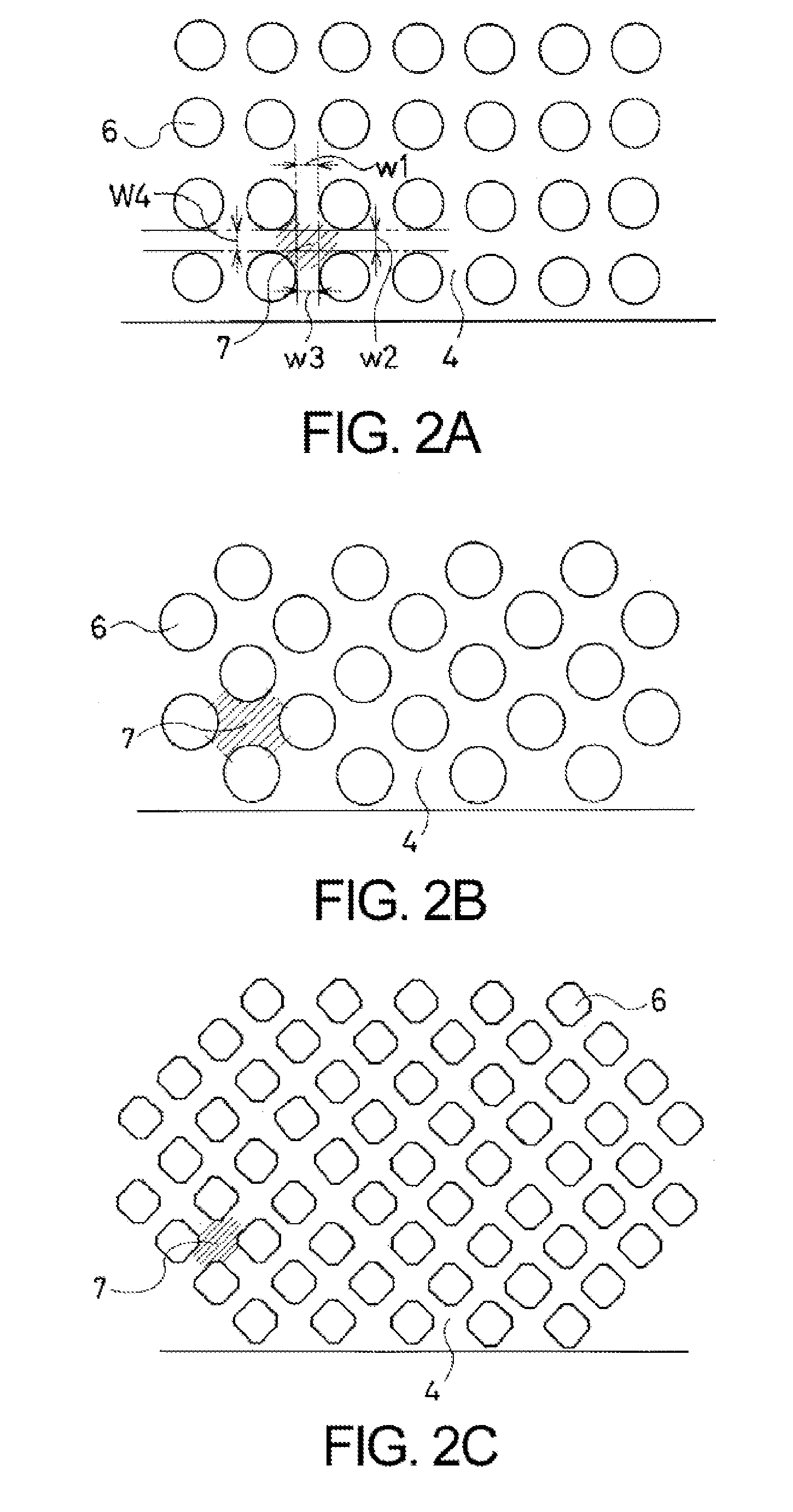
[0017]With the present technology, sipes or small holes are provided in block-like land portions of a tread, and multiple protrusions are disposed having a height that is less than a depth of the sipes or small holes. Moreover, the multiple protrusions are disposed so as to form a shape wherein a flow path width increases at a flow path convergence point where flow paths formed in a mesh-like shape between the protrusions converge from at least three directions. Thereby, high water pickup effect and edge effect can be obtained when traveling on icy and snowy road surfaces, even at initial use of a studless pneumatic tire. Additionally, a studless pneumatic tire is provided in which, after initial use and even after the effectiveness of the multiple protrusions has declined, the sipes or small holes enable superior edge effect to be displayed and enable braking ability on ice and steering stability on snow.

Problems solved by technology

However, generally, if a rubber layer including the filler and / or microscopic voids is exposed on a tire surface, which directly contacts a mold when vulcanizing / curing the rubber, said rubber layer will not be formed.
However, in many cases, the subject matter of this proposal does not sufficiently display water removal or draining as a result of providing the narrow grooves, and thus, cannot be considered to be satisfactory.

Method used


Image

  • Pneumatic tire
  • Pneumatic tire
  • Pneumatic tire

Examples


examples

[0034]Six types of pneumatic tires (Conventional Example, Comparative Examples 1 to 3, and Working Examples 1 and 2) were fabricated test tires having a common tire size of 215 / 60R16. The presence / absence of, shape / height of, and area ratios of the protrusions varied for each tire. Sipes were provided having a depth of 6 mm, an amplitude of 0.8 mm, and a pitch of 2.4 mm.

[0035]Each of the six types of tires were rim assembled on a 16×7J size rim (major rim), inflated to an air pressure of 220 kPa, and mounted on a 2000 cc sedan (FR vehicle). Then, the following traveling tests were conducted on a test course. The test results are as shown in Table 1. The pneumatic tires of the present technology had braking performance on ice and steering stability on snow and displayed extremely superior performance factors beyond those of the pneumatic tires of the Conventional Example and the Comparative Examples.

[0036](1) Braking Ability on Ice Test:

[0037]Braking distances required to come to a c...


PUM


Abstract

A pneumatic tire including, on a tread surface, rib-like land portions partitioned by a plurality of main grooves and / or a plurality of block-like land portions partitioned by lug grooves extending in a tire width direction, wherein sipes or small holes are provided in the land portions, multiple protrusions are disposed having a height that is less than a depth of the sipes or small holes, and the multiple protrusions are disposed so as to form a shape wherein a flow path width increases at a flow path convergence point where flow paths formed in a mesh-like shape between the protrusions converge from at least three directions, and a ratio of an area of the multiple protrusions to an area of a block-like land portion is 0.5 or greater and 0.9 or less.

Description

PRIORITY CLAIM[0001]Priority is claimed to Japan Patent Application Serial No. 2010-055401 filed on Mar. 12, 2010.BACKGROUND[0002]1. Technical Field[0003]The present technology relates to a pneumatic tire that is a studless tire having enhanced traveling performance on ice at initial use.[0004]2. Related Art[0005]Pneumatic tires known as “studless tires” have been proposed and put into actual use that have enhanced performance factors such as braking ability on ice and steering stability on snow when traveling on icy and snowy road surfaces.[0006]Some studless tires use tread compounds containing fine protrusions as a filler so as to obtain an edge effect on icy surfaces, and some use rubber including fine voids so as to obtain a water pickup effect and an edge effect.[0007]However, generally, if a rubber layer including the filler and / or microscopic voids is exposed on a tire surface, which directly contacts a mold when vulcanizing / curing the rubber, said rubber layer will not be f...

Claims


Application Information

Patent Timeline
IPC IPC(8): B60C11/12
CPCB60C11/12B60C2011/1213B60C11/1376B60C11/11B60C11/1259
Inventor FURUSAWA, HIROSHI
Owner YOKOHAMA RUBBER CO LTD
Learn More