
Auxiliary tank and mains water supply system

Active Publication Date: 2011-09-15
GRAY IAN
View PDF3 Cites 4 Cited by
  • Summary
  • Abstract
  • Description
  • Claims
  • Application Information

AI Technical Summary

Benefits of technology

[0006]A water supply system according to the invention permits the use of mains water and water stored in an auxiliary reservoir (tank) to be supplied to a building's reticulation system, while maintaining separation between the two water sources, with minimal pressure loss despite the different water supply pressures versus the flow characteristics of the mains and the pump.

Problems solved by technology

This end of the shuttle is therefore unbalanced with respect to pressure at the auxiliary inlet port.
When this condition exists, the unbalanced pressure on the shuttle forces it to move.
A minor interruption in the supply of water may be experienced during the switching of the valve.

Method used


Image

  • Auxiliary tank and mains water supply system
  • Auxiliary tank and mains water supply system
  • Auxiliary tank and mains water supply system

Examples


Embodiment Construction

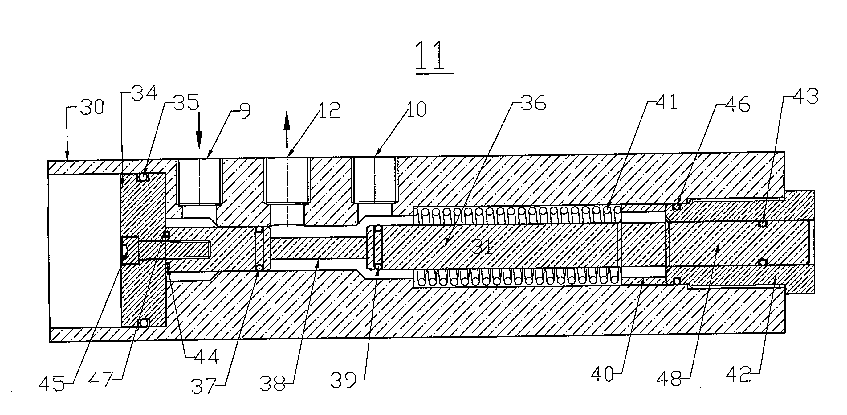
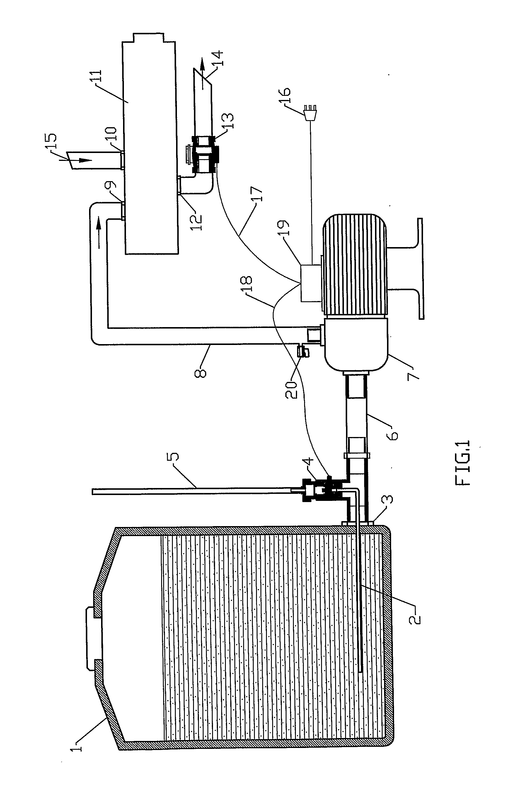
[0023]FIG. 1 illustrates a water supply system constructed according to the principles and concepts of the invention. Shown is an auxiliary water tank (1) for storing an auxiliary supply of water. The auxiliary water tank (1) accumulates runoff rain water from a roof, or can store water pumped therein from another source. The auxiliary tank (1) is equipped with an outlet port (3) located at the bottom of the tank (1). The outlet port (3) is connected by a conduit (6) to a pump (7). The pump (7) is preferably driven by an electric motor (not shown). A tube (2) protrudes through the outlet port (3) of the tank (1) and is connected to a level detection system, shown as a float system (4). The tube (2) connects the float system (4) to the water in the auxiliary tank (1) so that the static head in the tank (1) can be detected without being affected by the dynamic flow that would otherwise adversely affect the float system (4) if it were directly connected to the conduit (6). Connected to...


PUM


Abstract

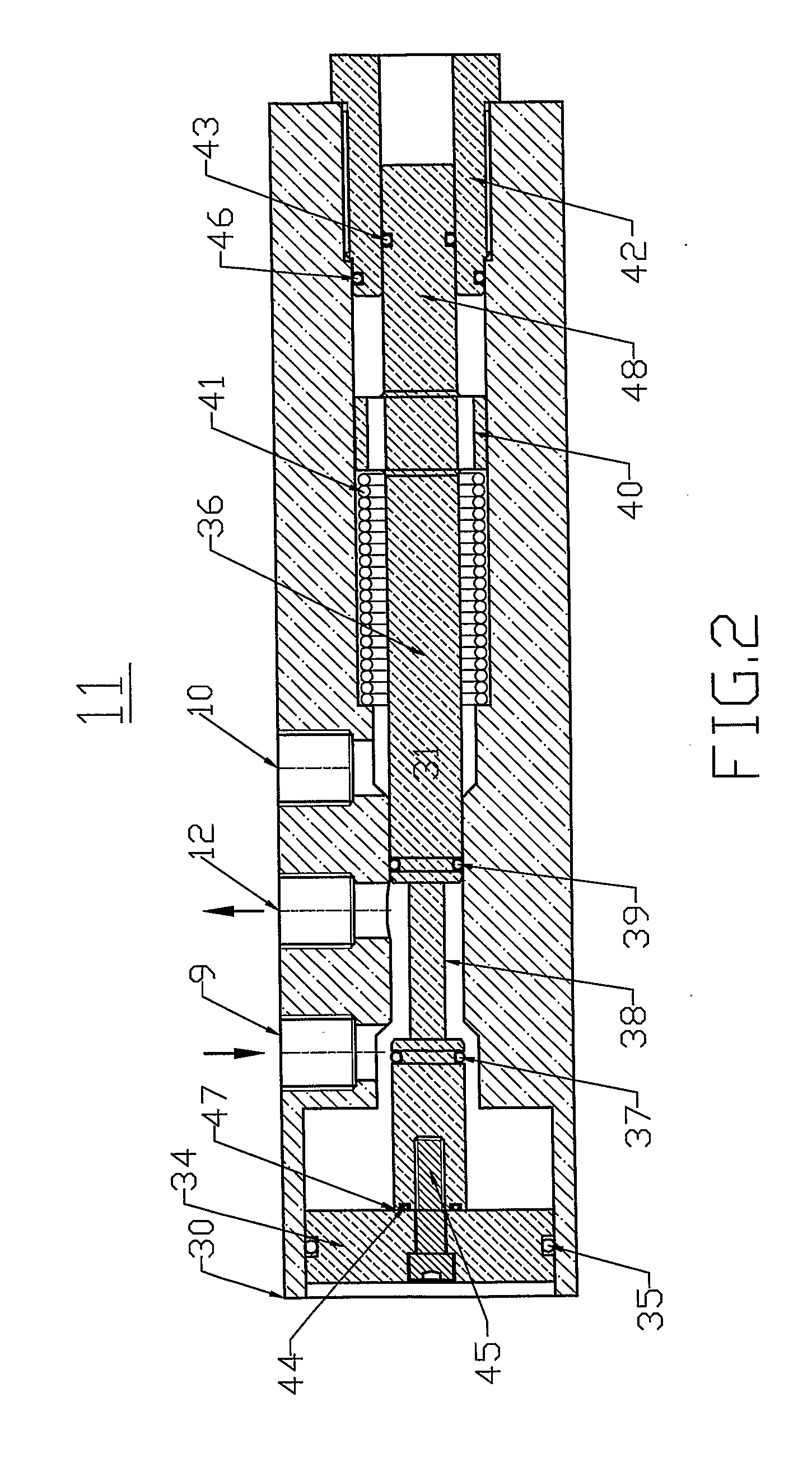
A water supply system that supplies water to a plumbing system from either a mains supply, or an auxiliary supply. In a default state, a shuttle valve is pressure balanced and couples water from the mains supply to the plumbing system via mains inlet port and outlet port, and in another state the shuttle valve is pressure unbalanced and moved so that auxiliary water is coupled to the plumbing system via an auxiliary inlet port and the outlet port of the shuttle valve. Water is drawn from an auxiliary tank and coupled to the plumbing system when two conditions exist, namely when water is demanded, as sensed by flow sensor, and when water is available from the auxiliary supply, as sensed by float system. Water pressure at the auxiliary inlet port causes the shuttle to move from the default state and couple water from the auxiliary inlet port to the outlet port and thus to the plumbing system. When either of the two conditions are not met, the shuttle valve remains in the default state and couples mains water from the mains inlet port to the outlet port and thus to the plumbing system.

Description

BACKGROUND[0001]Water is a resource that is necessary for the daily existence of living things. A supply of water is generally provided to every building, whether it be a residential home in the city or country, an office building, or other habitat where people either.live or work. Water is usually stored in a reservoir, such as a tower, lake, river, etc., and then purified and coupled under pressure through a pipe network to the buildings. The pipe network can be a large main from which smaller laterals are routed to the individual buildings. With such a network, fresh water is constantly available to every person by simply turning on a faucet, or the like.[0002]The storage of water in a reservoir and the purification of the same comes at a cost to the consumer. In contrast, rain water is available in many regions of the world and when collected from a rooftop and stored in an auxiliary tank, or other container near the building, can be used in a very cost effective manner. Indeed,...

Claims


Application Information

Patent Timeline
IPC IPC(8): F16K11/02
CPCE03B7/04E03B7/075G01F23/76G01F23/68G01F23/74F16K11/07Y10T137/0379Y10T137/2567Y10T137/87571Y10T137/87676
Inventor GRAY, IAN
Owner GRAY IAN
Learn More