
Air movement system

a technology of air movement and air flow, which is applied in the direction of positive displacement liquid engines, instruments, machines/engines, etc., can solve the problems of unnecessarily increasing the cost of both the system and its operation, affecting the air flow of the system, and affecting the operation of the system, etc., to achieve the effect of improving the air movemen

Inactive Publication Date: 2011-09-08
BRINK CLIMATE SYST
View PDF4 Cites 10 Cited by
  • Summary
  • Abstract
  • Description
  • Claims
  • Application Information

AI Technical Summary

Benefits of technology

[0016]In accordance with embodiments of the invention, an object is to provide an enhanced air movement system, in which an air flow rate through a centrifugal fan unit is not dependent on the load or resistance of the air movement system before and after the centrifugal fan unit.
[0022]The centrifugal fan unit, in particular with blades that are cured backward with respect to the rotational direction of the fan, proved highly efficient in a ventilation system. In order to provide a constant flow, even after passing of time which usually influences the air resistance of the system and the inlet and outlet ducts, the constant flow can be maintained.
[0025]In particular, it was found that the flow rate of the air movement system could be controlled independent of the amount of resistance in the inlet or outlet, and independent if the resistance (e.g., filter, heat exchanger, etc.) was placed before the inlet or before the outlet. In particular, it was found that proper placement of pressure sensors made it possible to economically use a centrifugal pump in an air movement system.

Problems solved by technology

This adds unnecessarily to the expense of both the systems and their operation.
In addition, filters used in some systems can become clogged with particulates, making them more resistant to air flow over time.
This increased resistance may cause the air flow of the system to drop below acceptable levels unless it is precisely monitored and steps are taken to compensate for the increased resistance.
Unfortunately, many methods of measuring air flow in a ventilation system can dramatically decrease the efficiency of the system.
To provide an air movement system, the centrifugal fan unit is build into a housing in an uneconomical way.
Again, setting such a unit to deliver a constant flow independent of its used and external resistance is a problem.
This, however, does not provide a constant flow of air.
This again does not provide an accurate flow.
The flow rate, however, proved not to be constant enough.
In particular when the resistance of the inlet and outlet system varies or the units are used for different duct systems and air treatment systems, it proved difficult to set and maintain a constant flow.

Method used


Image

  • Air movement system
  • Air movement system
  • Air movement system

Examples


Embodiment Construction

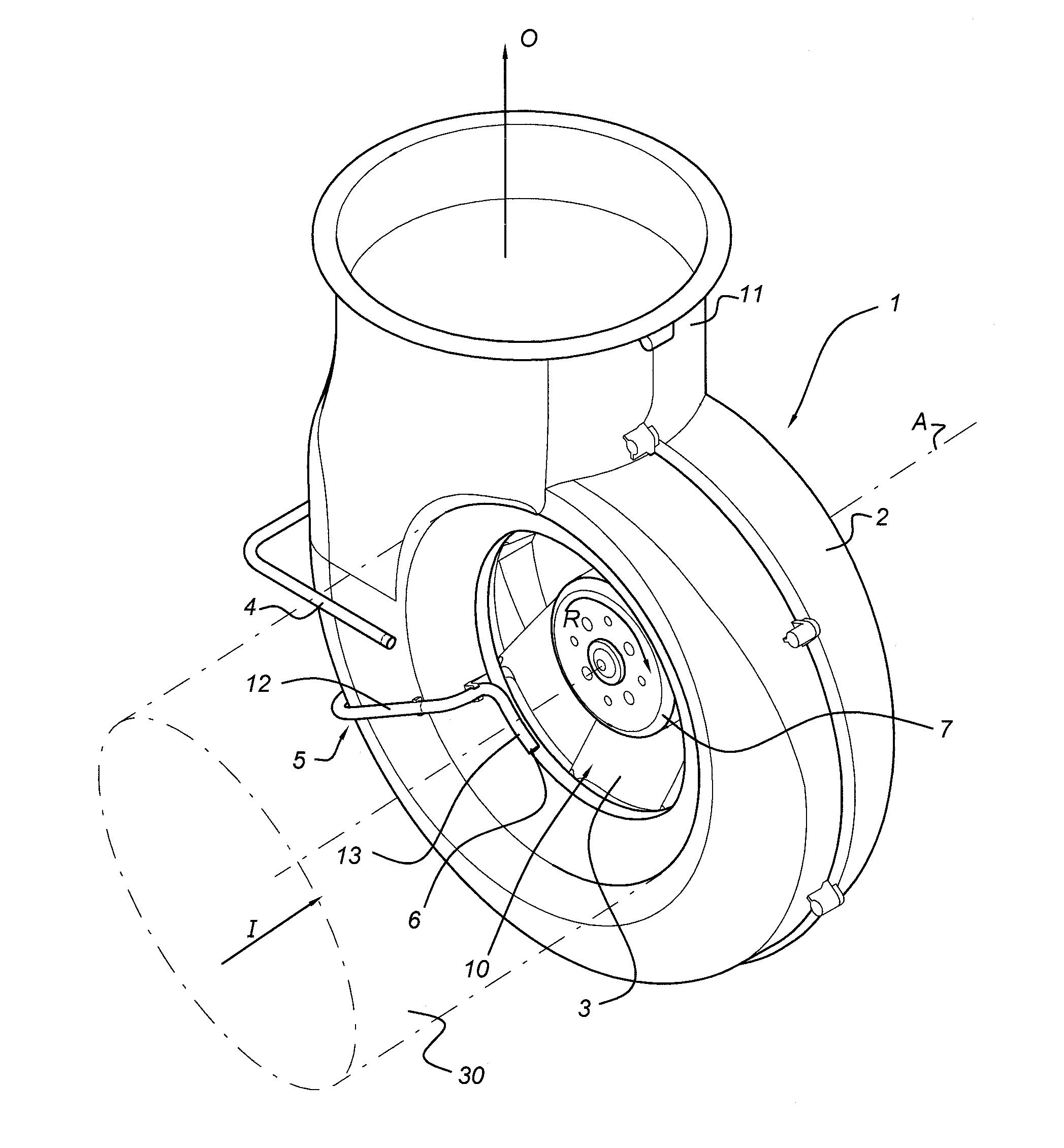
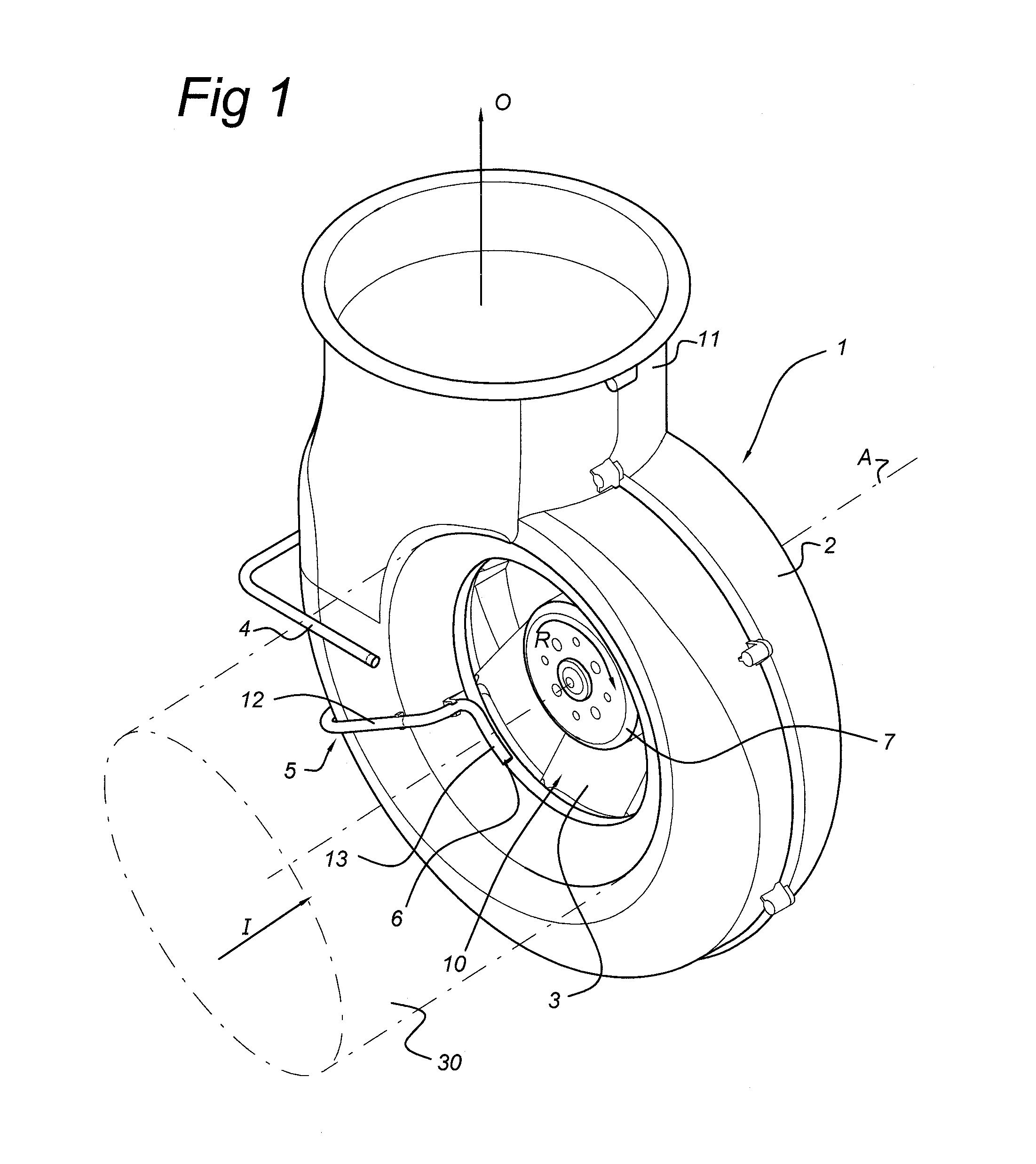
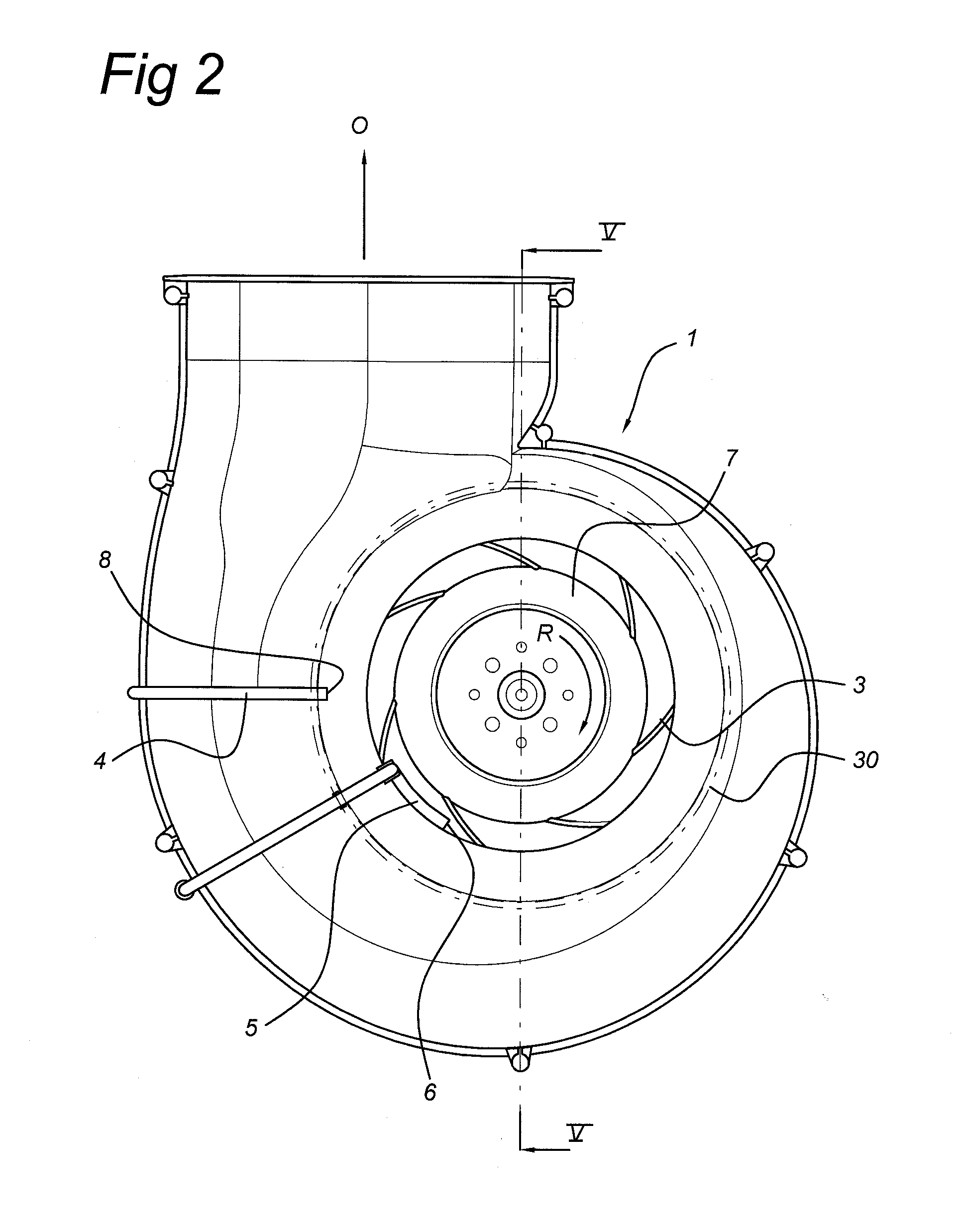
[0043]Example FIG. 1 shows a perspective view of centrifugal pump 1 with a centrifugal fan unit. Example FIGS. 2-4 show several views of the centrifugal pump shown in example FIG. 1. Example FIG. 5 shows a cross section of the centrifugal pump indicated in example FIG. 2.

[0044]Centrifugal pump 1 has a spiral or annular casing 2. Spiral casing or house 2 defines part of inlet duct 10. The direction of incoming air is indicated by arrow I. Example FIGS. 3 and 4 also provide views of the air flow direction I of the incoming air. Provided at the smallest cross-section of inlet duct 10 is fan 3. As illustrated in example FIG. 2, when fan 3 is in operation, its rotational direction is clockwise as indicated by arrow R. House 2 further defines outlet 11. The direction of the outgoing air at outlet 11 is indicated by arrow O. Example FIGS. 2 and 4 also provide views of the air flow direction O of the outgoing air. The direction of outgoing air O is perpendicular to the direction of incoming...


PUM


Abstract

The invention relates to an air movement system comprising a centrifugal fan unit, wherein the centrifugal fan unit comprises a centrifugal fan coupled to a drive unit, a control unit operationally coupled to said drive unit, an inlet piece forming a inlet duct to the centrifugal fan, which inlet duct has an end facing the centrifugal fan, and an outlet duct, wherein the inlet piece is provided with a first pressure tap and a second pressure tap, the second pressure tap being positioned at distance from the end of the inlet duct facing the centrifugal fan, and the control unit is configured to measure a pressure difference between the first and second pressure tap and to control the centrifugal fan in dependence of the measured pressure difference, characterized in that the first pressure tap is positioned at the end of the inlet duct facing the fan, and in that said control unit is adapted to maintain a set airflow rate out of said outlet duct based on said measured pressure difference via controlling of the rotational speed of said centrifugal fan.

Description

CROSS-REFERENCE TO RELATED APPLICATIONS[0001]The present application claims priority under 35 U.S.C. §119 to European Patent Application No. 10152302.5 (filed on Feb. 1, 2010), the full contents of which is hereby incorporated by reference in its entirety.FIELD OF THE INVENTION[0002]Embodiments of the invention relate to an air movement system, more particular, to a centrifugal fan unit for providing an air flow in the air movement system, more particular to a centrifugal fan unit with backward-curved blades. Embodiments of the invention further pertains to a ventilation system for a building, in particular, a utility building or a residential building, the ventilation system including the centrifugal fan unit.BACKGROUND OF THE INVENTION[0003]Ventilation systems in many commercial settings are required, either by regulations or by functional specifications, to have a certain minimum flow rates. For example, in commercial buildings, a minimum level of air flow is required to maintain...

Claims


Application Information

Patent Timeline
Patent Type & Authority Applications(United States)
IPC IPC(8): F04B49/00
CPCF04D25/08F04D27/001F04D27/004F05B2270/3015Y02B30/746F24F2011/0042G01F1/34G01F1/363F24F11/0079F05D2270/301F24F2110/40F24F11/77Y02B30/70
Inventor HANEWALD, RUDOLF
Owner BRINK CLIMATE SYST
Learn More