Inkjet printer operating a binary continuous-jet with optimum deflection and maximised print speed

Inactive Publication Date: 2011-09-08
MARKEM IMAJE LTD
View PDF8 Cites 4 Cited by
  • Summary
  • Abstract
  • Description
  • Claims
  • Application Information

AI Technical Summary

Benefits of technology

[0043]The use of a printer according to the invention is thus advantageous by using solely the zones C1 and C3. The deflection level is thus almost binary, which greatly facilitates the design and dimensioning for installation of the gutter and more precisely its drop- or jet-intercepting edge, and avoids risks of interference created by drops whose deflection maybe poorly controlled.
[0054]Starting from the device described with two electrodes, the inventors also found that the number n of electrodes can be increased to 4, 6 . . . so as to increase the amplitude of deflection. The block of electrodes comprises a plurality of n electrodes (pair A, pair B) of individual height He separated individually by a dielectric of height Hd in order to increase the angle of deflection of the deflected jet segments.
[0056]For the principle of printing by inkjet deflection, the invention with the plurality of electrodes n offers the advantages of being able to optimise the parameters of drop production rate (print speed) and the amplitude of the deflection in a relatively independent manner.
[0060]a binary deflection level to facilitate the placement of the gutter and therefore the recovery of the non-printed jets (or segments).
[0065]In other words, the breaking of the jet that delimits the upstream part of the segment Hc3 occurs only when the downstream end of the segment Hc3 covers the first electrode He and the dielectric Hd that extends it. This advantageous configuration makes it possible to deflect the downstream end of the segment Hc3 with the first electrode (n=1 in FIG. 4). In this way an electrical looping back by the earthed nozzle plate is achieved without waiting to form a dipole by means of the first pair of electrodes (n=1 and n=2 in FIG. 4).
[0066]According to a first variant, the jet segments deviated to the minimum extent are those carrying out the printing. The generator can then deliver pulses at the first shorter period for printing. The time between pulses is less than or at maximum equal to Tc1. The duration of pulses maybe different in order to generate jet segments with different sizes, but all negligibly deviated or to the minimum. By printing drops with variable duration pulses and therefore variable sizes, it is thus possible to create different grey levels for a given printing, and therefore to increase the print quality.

Problems solved by technology

These guard drops, systematically interposed between the charged drops in order to limit interference, do not make it possible to print at the maximum speed of each jet given by the frequency of generation of the drops and the output of the jet.
This printing principle also leads to constraints relating to the formation of the drops and their interactions.
Because of this, the use of printable drops must be limited.
The major drawback of this approach is not optimising the print speed performance which is however essential in binary continuous jet technology.

Method used


Image

  • Inkjet printer operating a binary continuous-jet with optimum deflection and maximised print speed
  • Inkjet printer operating a binary continuous-jet with optimum deflection and maximised print speed
  • Inkjet printer operating a binary continuous-jet with optimum deflection and maximised print speed

Examples


Embodiment Construction

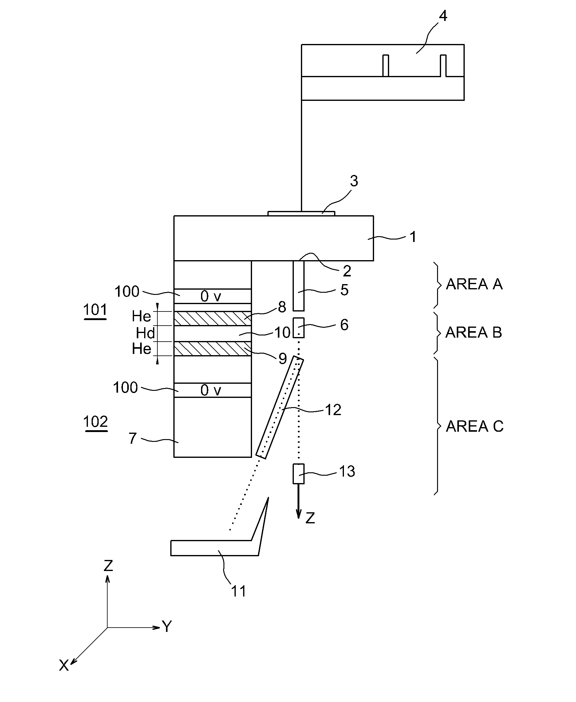
[0073]FIGS. 1 and 2 have been commented on in the preamble.

[0074]The references in FIGS. 1 and 2 designating the same elements have been repeated in FIG. 3.

[0075]FIG. 3 shows a preferred embodiment according to which the block of electrodes 100 comprises two pairs 81, 91 and 82, 92 of individual height He and separated from each other by dielectrics 101, 102 of identical height Hd.

[0076]The block 100 has a curved profile P that enables the deflected jet segments 12 to be at a substantially constant distance from the facing electrodes over the entire height of the block.

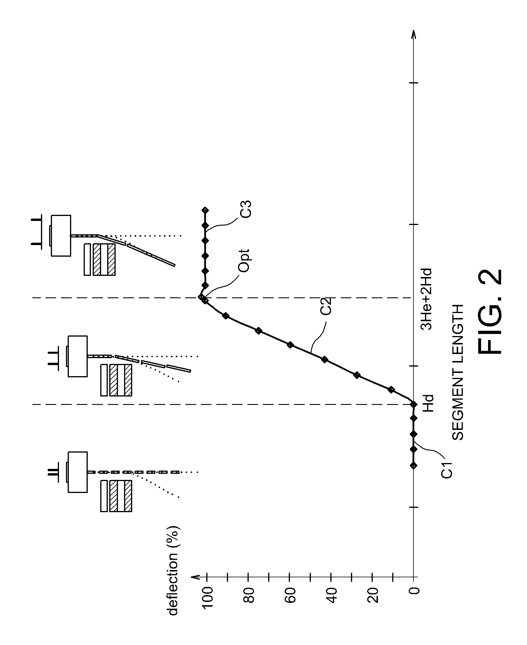
[0077]FIG. 4 presents the change in a deflected jet segment whose length tends naturally to decrease under the action of the surface tension 12A, 12B, 12i.

[0078]Every end 200 of a given jet segment (12C for example) undergoes a return force (capillary force) that mutually brings the ends together in order in the end to give a spherical shape to the jet segment, initially cylindrical in shape. The length of the segment...


PUM


Abstract

The invention concerns inkjet printers with binary continuous jet, the printing principle of which is based on the differential deflection of jets or jet segments. According to the invention, by virtue of a judicious selection of pulse periods of the electrical generator, the print speed of such printers is optimised while guaranteeing precision of the two deflection levels (binary).

Description

TECHNICAL FIELD[0001]The invention concerns inkjet printers operating with binary continuous jets, the printing principle of which is based on the differential deflection of jets or segments of jets.[0002]It relates more particularly to the optimisation of the print speed of such printers while guaranteeing precision of the deflection levels.PRIOR ART[0003]Ink-jet printing consists of producing and directing ink drops towards a print medium.[0004]Traditionally two different ink-jet printing technologies can be distinguished: drop on demand technology and continuous jet technology. Drop on demand technology is widespread in office printing applications, where the print speed is lower, whereas continuous-jet technology is used widely in the industrial printing field since it guarantees high productivity and good robustness in severe industrial environments. This continuous-jet technology can be broken down into two sub-classes, deviated continuous jet technology (deflection at multipl...

Claims


Application Information

Patent Timeline
IPC IPC(8): B41J2/02
CPCB41J2/105B41J2/095
Inventor BARBET, BRUNOJOLY, RUDY
Owner MARKEM IMAJE LTD
Why Eureka
Try Eureka