Optical pickup device and optical disc apparatus
- Summary
- Abstract
- Description
- Claims
- Application Information
AI Technical Summary
Benefits of technology
Problems solved by technology
Method used
Image
Examples
first embodiment
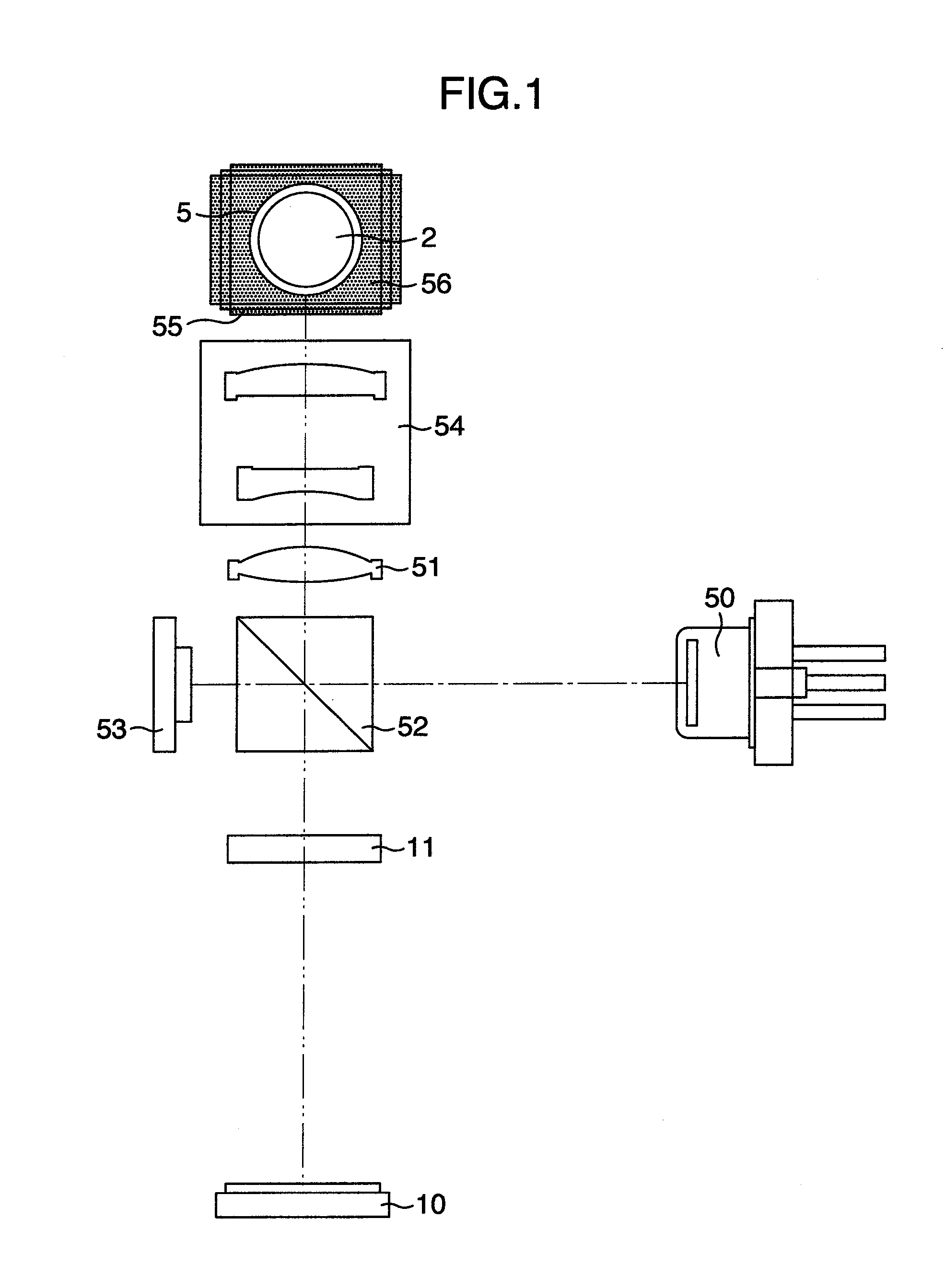
[0040]FIG. 1 illustrates an optical system of an optical pickup device according to a first embodiment of the present invention. Here, although a BD (Blu-ray Disc) will be described, a DVD (Digital Versatile Disc) or other recording systems may be optionally applicable. Note that layers of an optical disc include a recording layer of a recording optical disc and a reproducing layer of a reproduction-only optical disc in the following description.
[0041]An optical beam having a wavelength of approximately 405 nm is emitted from a laser diode 50 as divergent light. The optical beam emitted from the laser diode 50 is reflected by a beam splitter 52. Note that a portion of the optical beam passes through the beam splitter 52 and then enters a front monitor 53. Generally, in such a case that information is recorded on the recording type optical disc, the light amount of the laser diode is required to be controlled with a high degree of accuracy in order that a predetermined light amount o...
second embodiment
[0063]FIG. 11 illustrates light receiving parts of a photodetector of an optical pickup device according to a second embodiment of the present invention. A structural difference from the first embodiment is the photodetector 10 and the other structural elements of the second embodiment are similar to those of the first embodiment.
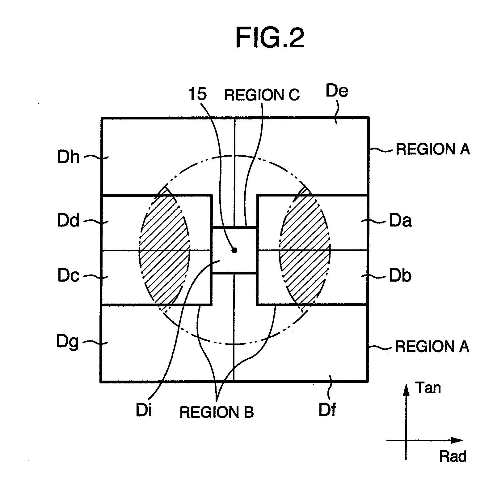
[0064]The grating 11 illustrated in FIG. 2 is formed by the regions De, Df, Dg, and Dh (region A) entered by only the zero-th order disc diffracted light of the disc diffracted light diffracted by the tracks on the optical disc, the regions Da, Db, Dc, and Dd (region B) entered by the zero-th order disc diffracted light and the ±first order disc diffracted light of the disc diffracted light, and the region Di (region C).
[0065]Suppose that a spectral ratio of the grating 11 is, for example, the zero-th order grating diffracted light: the +first order grating diffracted light: the −first order grating diffracted light=10:1:1. The photodetector 10 has a patter...
third embodiment
[0073]FIG. 16 illustrates light receiving parts of a photodetector of an optical pickup device according to a third embodiment of the present invention. A structural difference from the first embodiment is the photodetector 10 and the other structural elements of the second embodiment are similar to those of the first embodiment.
[0074]The grating 11 illustrated in FIG. 2 is formed by the regions De, Df, Dg, and Dh (region A) entered by only the zero-th order disc diffracted light of the disc diffracted light diffracted by the tracks on the optical disc, the regions Da, Db, Dc, and Dd (region B) entered by the zero-th order disc diffracted light and the ±first order disc diffracted light of the disc diffracted light, and the region Di (region C).
[0075]Suppose that a spectral ratio of the grating 11 is, for example, the zero-th order grating diffracted light: the +first order grating diffracted light: the −first order grating diffracted light=10:1:1. The photodetector 10 has a pattern...
PUM
 Abstract
Description
Claims
Application Information
 - R&D
- Intellectual Property
- Life Sciences
- Materials
- Tech Scout
- Unparalleled Data Quality
- Higher Quality Content
- 60% Fewer Hallucinations
Browse by: Latest US Patents, China's latest patents, Technical Efficacy Thesaurus, Application Domain, Technology Topic, Popular Technical Reports.
© 2025 PatSnap. All rights reserved.Legal|Privacy policy|Modern Slavery Act Transparency Statement|Sitemap|About US| Contact US: help@patsnap.com


