
Motion control system with digital processing link

a technology of motion control and processing link, applied in the field of active vibration systems, can solve the problems of reducing affecting the transmission speed of the transmission, so as to reduce the generation of electromagnetic interference, increase the transmission speed, and evenly spread the energy content of the transmission

Inactive Publication Date: 2011-08-25
LORD CORP
View PDF55 Cites 100 Cited by
  • Summary
  • Abstract
  • Description
  • Claims
  • Application Information

AI Technical Summary

Benefits of technology

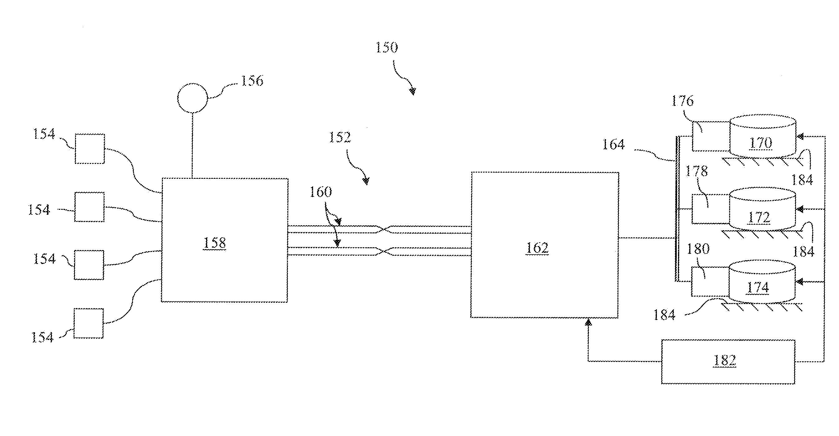
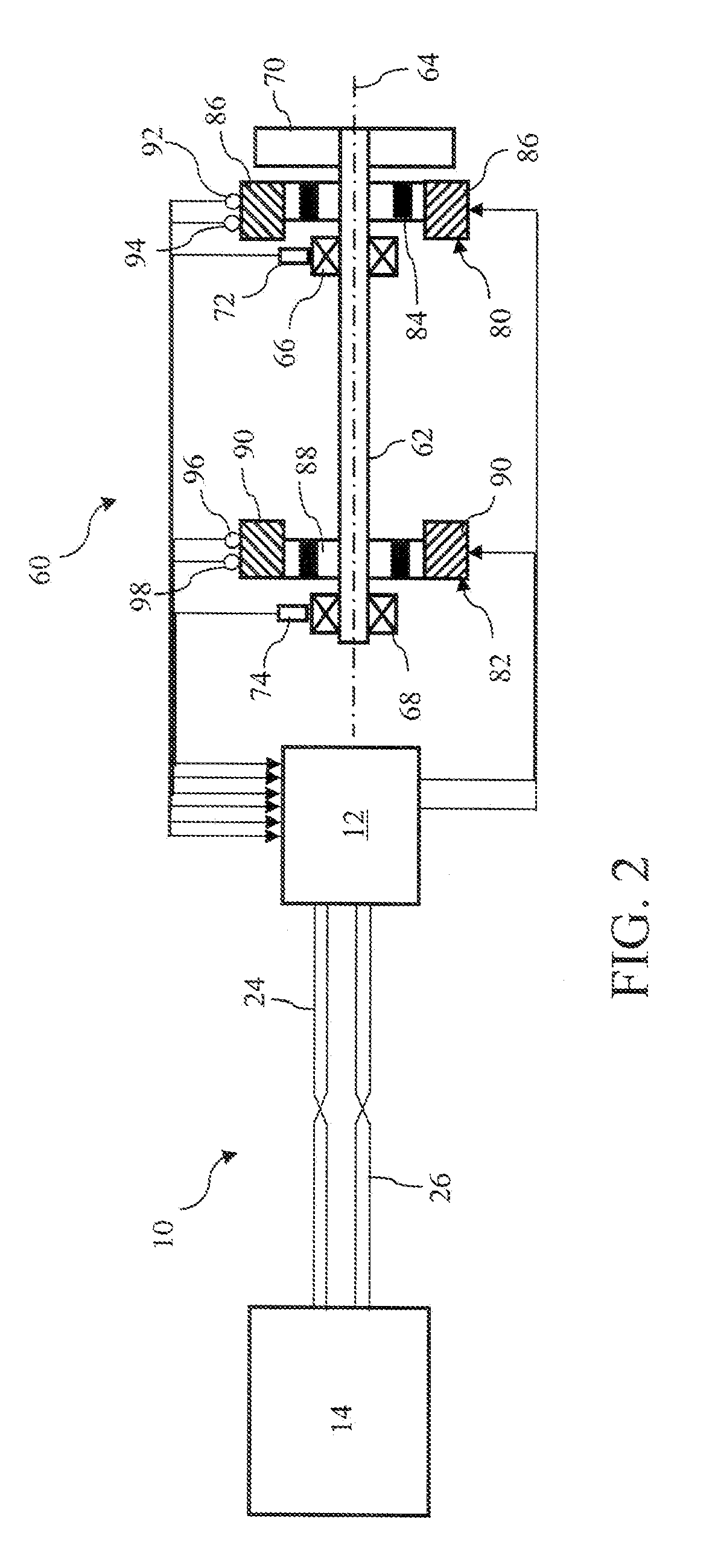
Preferred implementations of the invention provide secure data exchanges between groups of sensors and controllers of active vibration and balancing systems under a digital protocol that is largely impervious to local electromagnetic disturbances, electrical surges, and other environmental influences. Signals from multiple sensors combine at a transfer station under the digital protocol and transmit together over common wiring pairings to a base station associated with the controller. The wire pairings, which preferably include pairings for both transmitting and receiving data, also convey error-checking communications in accordance with the digital protocol and also provide for transmitting electrical power. Although signals from multiple sensors are collectively transmitted over the same wire pairings, transmission speeds can be increased while more evenly spreading the energy content of the transmissions to reduce the generation of electromagnetic interference that could otherwise affect other communications.
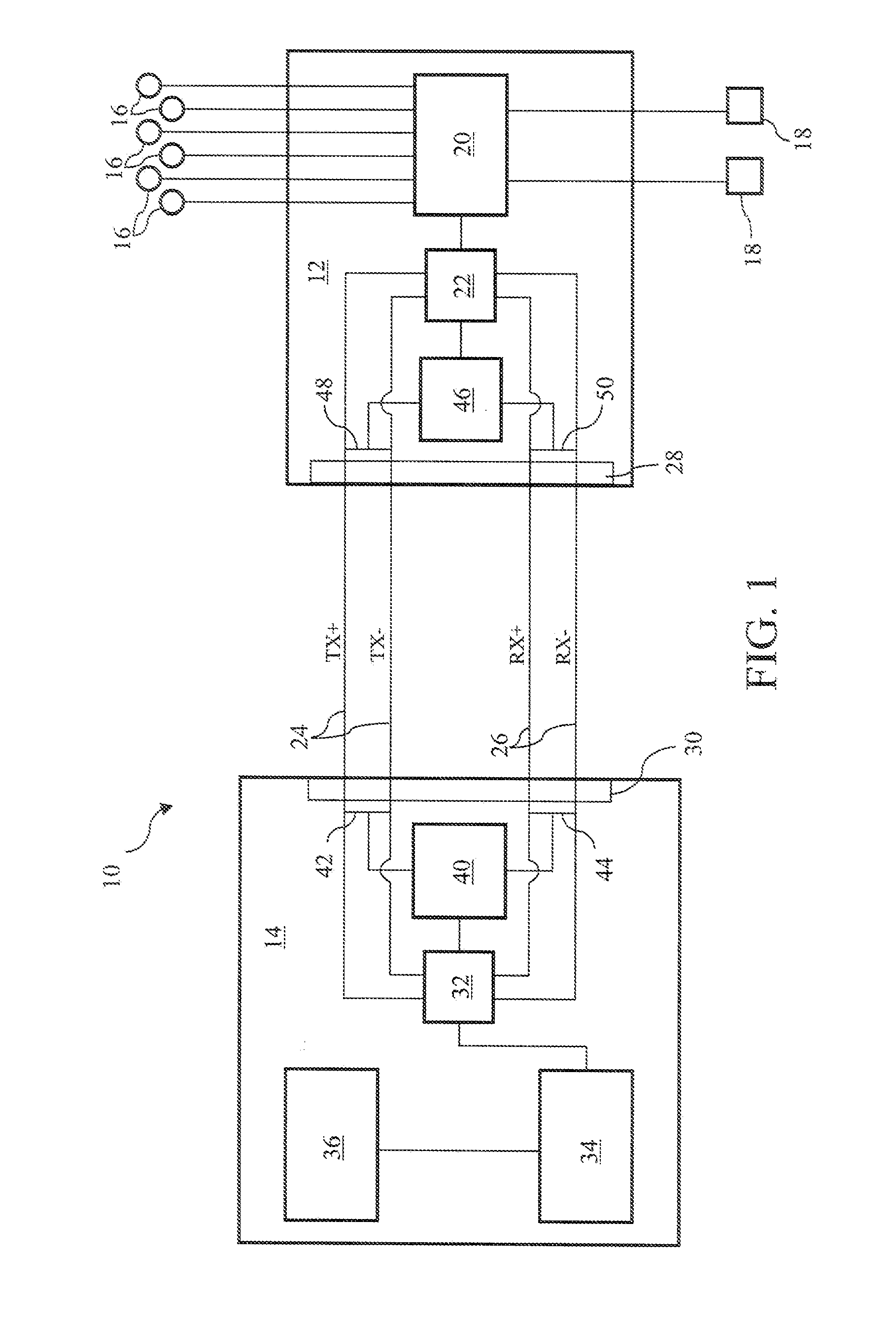
Preferably, the communication node of the transfer station converts the collective signal into a series of frames having a prescribed format for monitoring and resending errant transmissions. In addition, the communication node of the transfer station preferably spreads the energy content of the collective signal over the data transmit lines to reduce electrical interference. The communication node of the transfer station also preferably includes protection circuitry in the form of a disconnect to avoid transmitting lightning surges. The transfer station can include an analog to digital converter to convert analog signals from the sensors into digital signals.
The actuator preferably amplifies force at one or more tuned frequencies. For example, the actuator can include one or more eccentric masses that are rotatable about a rotation axis or a translatable mass that is reciprocable along a linear axis. The plurality of sensors can include accelerometers used for sensing vibration. The transfer station is preferably positioned for reducing an average distance between the transfer station and the plurality of sensors.
Preferably, the sensors are distributed according to results from an optimization study. The transfer station is preferably located among the sensors for reducing an average distance between the sensors and the transfer station.

Problems solved by technology

Wiring to and from the sensors for delivering power to the sensors and for communicating data from the sensors particularly over large distances can add considerable weight and bulk to active vibration and balancing systems and subject the transmissions to environmental electromagnetic influences.
Transmissions from sensors with low signal levels or over long runs of wires are particularly susceptible to such electromagnetic disturbances.
Environments of machine tools and aircraft, requiring active vibration or balancing systems, often contain strong electromagnetic fields that can disrupt the transmission of sensor data over even short distances of travel.
Similar problems can exist for data exchanges with actuators, particularly for actuators that are separated from their controllers or susceptible to intervening electromagnetic fields.

Method used


Image

  • Motion control system with digital processing link
  • Motion control system with digital processing link
  • Motion control system with digital processing link

Examples


Embodiment Construction

Additional features and advantages of the invention will be set forth in the detailed description which follows, and in part will be readily apparent to those skilled in the art from that description or recognized by practicing the invention as described herein, including the detailed description which follows, the claims, as well as the appended drawings.

Reference will now be made in detail to the present preferred embodiments of the invention, examples of which are illustrated in the accompanying drawings.

An exemplary digital processing link 10 depicted in FIG. 1 interconnects a transfer station 12 with a base station 14. The transfer station 12 provides a common routing for input signals from a plurality of sensors 16 and for output signals to a plurality of actuators 18. Within the transfer station a multiplexer / demultiplexer 20, such as a field programmable gate array of a digital multiplexer, combines the input signals from the plurality of sensors into a single collective sen...


PUM


Abstract

A digital processing link for a vibration control system collects sensor signals at a transfer station and combines the sensor signals into a collective signal that is transmitted under a digital communications protocol to a base station. The sensor signals are separated at the base station and individually processed to produce one or more output control signals to actuators for counteracting the measured vibration.

Description

TECHNICAL FIELDThe invention relates generally to active vibration systems, which counteract ongoing vibrations, and active balancing systems, which counteract the onset of vibrations, particularly for applications in the aerospace and machine tool industries, and including power and communication links within the systems, such as links between sensors, controllers, and actuators.BACKGROUND OF THE INVENTIONActive vibration and balancing systems generally require a plurality of sensors for sensing vibrations, motions, and other environmental or performance variables to provide feedback to system controllers for controlling actuators. For example, accelerometers monitor vibrations, tachometers monitor the speed of rotating parts, such as propellers or machine spindles associated with the generation of the vibrations, and position sensors monitor operating performance of actuators.Wiring to and from the sensors for delivering power to the sensors and for communicating data from the sen...

Claims


Application Information

Patent Timeline
Patent Type & Authority Applications(United States)
IPC IPC(8): G05D19/02G06F1/26
CPCG05B2219/25135G05B19/404F16F15/00G05B13/00G05B19/00
Inventor HILDEBRAND, STEPHEN F.SWANSON, DOUGLASFERGUSON, MATTHEWSMITH, MATTHEW A.
Owner LORD CORP
Learn More