
Bracket system and method for planning and producing a bracket system for the correction of tooth malpositions

a bracket system and malposition technology, applied in brackets, dental tools, dental prosthetics, etc., can solve the problems of inaccurate bracket transfer, manual transfer of brackets by dentists, and inability to achieve treatment in the desired manner, so as to improve the placement of brackets on teeth

Inactive Publication Date: 2011-08-25
SIRONA DENTAL SYSTEMS
View PDF18 Cites 81 Cited by
  • Summary
  • Abstract
  • Description
  • Claims
  • Application Information

AI Technical Summary

Benefits of technology

[0014]The bracket system comprises a plurality of brackets, an arch, and a plurality of platelets. Unlike prior brackets, the platelets are first bonded to the respective labial or lingual tooth surfaces, the positions of the platelets are scanned in a three-dimensional optical image and a three-dimensional radiograph, and prior, conventional brackets are then provided with a recess on a bonding surface of the brackets, which recess matches the shape of the platelets. In the next step, the bonding surface of the prepared bracket is provided with a layer of bonding material, and the prepared brackets are positioned on the platelets and bonded to the tooth surface. As a result, more precise positioning of the brackets on the patient's teeth is achieved than when using the prior method.
[0054]Thus positioning of the bracket on the tooth is improved since the bracket lies exactly on a par with the tooth, as it rests exactly against the tooth surface.

Problems solved by technology

A problem of erroneous bonding often occurs with the use of known bracket systems.
In such systems, the brackets are not precisely bonded to the patient's teeth at the ideal positions intended for the brackets so that the treatment cannot achieve its goal in the desired manner.
The drawback of this method is that the transfer of the brackets by means of transfer trays is carried out manually by the dentist and is inaccurate.
Erroneous positioning is due to the fact that the transfer trays are inadequately adapted by the dental technician to match the tooth surface, or they are deformed during removal from the master model, or they are incorrectly applied to the patient's teeth by the dentist.
The drawback of this method is that positioning of the brackets by means of transfer trays is associated with the aforementioned problems.
The drawback of this method is that it is only possible to keep the distance of the bracket from the tip of the tooth and it is thus not possible to achieve precise three-dimensional positioning of the brackets in relation to the depth, the lateral distance, and the relative angle between the alignment of the bracket and that of the respective tooth.

Method used


Image

  • Bracket system and method for planning and producing a bracket system for the correction of tooth malpositions
  • Bracket system and method for planning and producing a bracket system for the correction of tooth malpositions
  • Bracket system and method for planning and producing a bracket system for the correction of tooth malpositions

Examples


Embodiment Construction

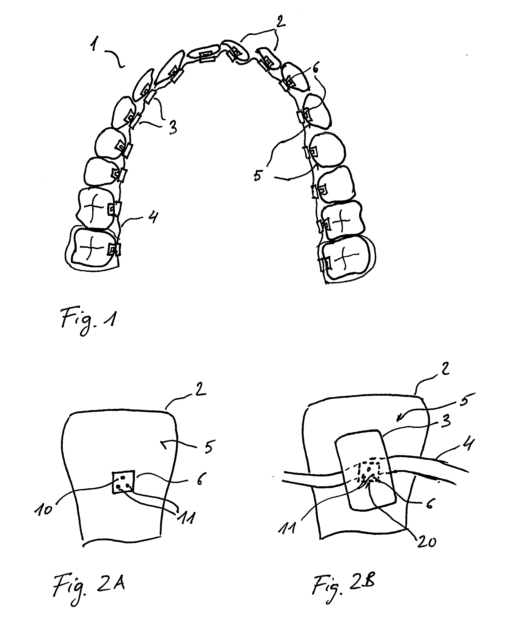
[0067]FIG. 1 is a sketch of the bracket system 1 for correcting malpositions of a patient's teeth 2. The bracket system 1 comprises a plurality of brackets 3 and an arch 4 extending along the inner surfaces of the row of teeth. An embodiment of the bracket system for the labial or buccal side of the patient's teeth 2 is likewise possible, for which purpose however, special buccal brackets are used. Platelets serving to position the brackets 3 are attached to the inner, lingual surfaces of the patient's teeth 2 to be corrected. The method for positioning the brackets is described below in greater detail.

[0068]The basic principle can be divided into the following steps: In the first step, the platelets 6 are bonded to the patient's teeth 2. In the second step, an optical three-dimensional image and, optionally, a three-dimensional radiograph of the patient's teeth together with the platelets 6 bonded thereto are created. The positions of the platelets 6 relative to the teeth are ident...


PUM


Abstract

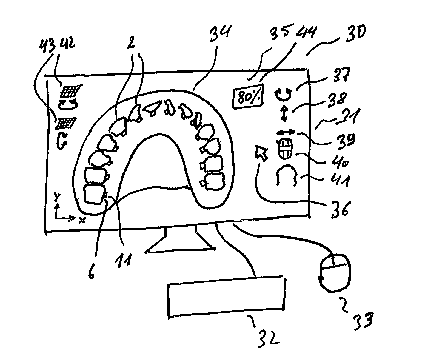
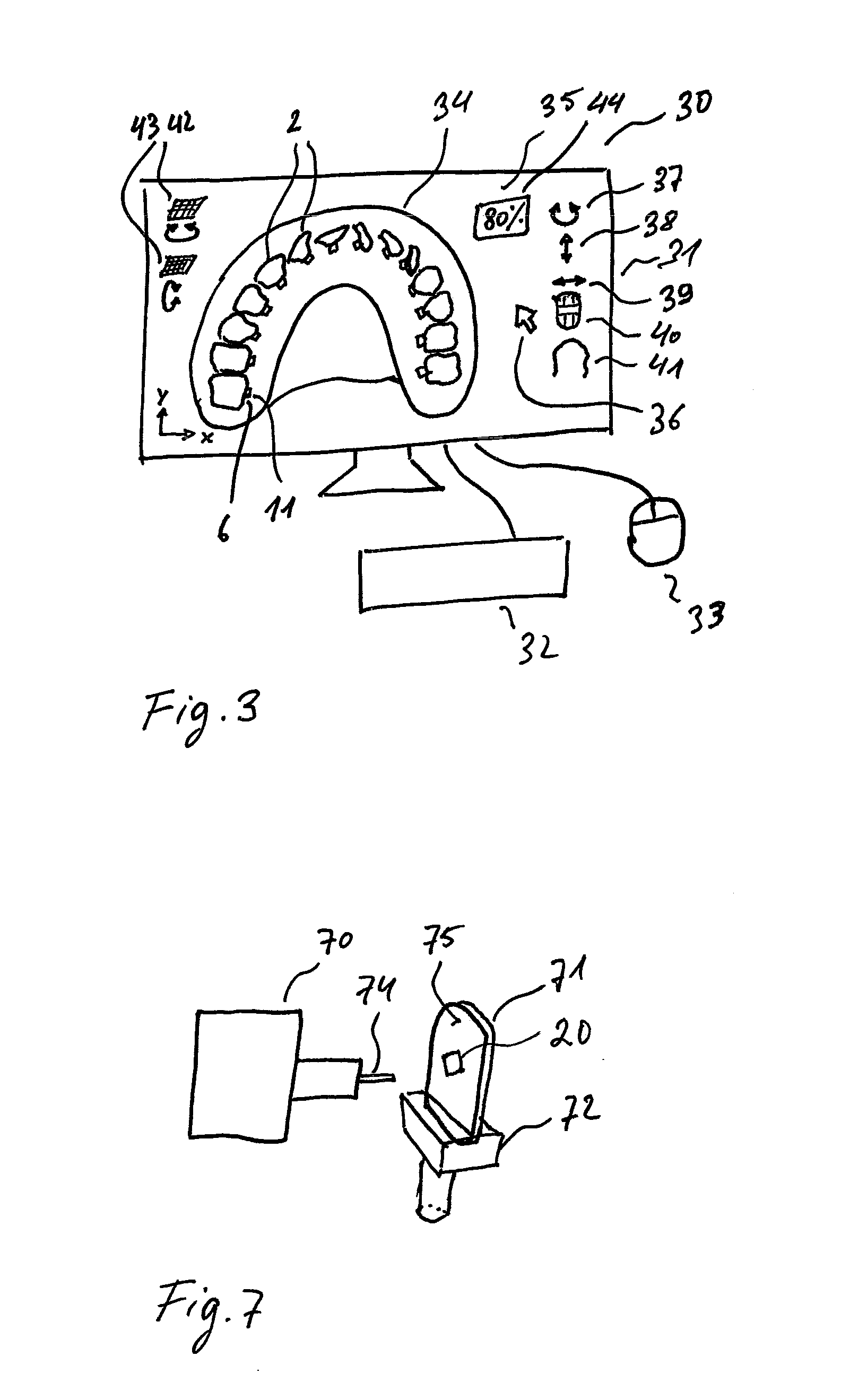
The invention relates to a method for planning a bracket system (1) for the correction of malpositions of teeth (2), comprising a plurality of brackets (3) and an arch (4) wherein at least one platelet (6) per tooth is mounted on certain tooth surfaces (5) of the teeth to be corrected (2), a three-dimensional optical image (50) of the tooth region to be treated is created, the platelets (6) have registration elements (10) comprising registration points (11) and the registration points (11) have a characteristic form for registration in the three-dimensional optical image (50)

Description

TECHNICAL FIELD[0001]The invention relates to a bracket system and a method for planning this bracket system for the correction of malpositions of teeth, which bracket system comprises a plurality of brackets and an arch.STATE OF THE ART[0002]A problem of erroneous bonding often occurs with the use of known bracket systems. In such systems, the brackets are not precisely bonded to the patient's teeth at the ideal positions intended for the brackets so that the treatment cannot achieve its goal in the desired manner.[0003]A number of solutions for preventing the possibility of erroneous bonding are known in the prior art.[0004]One option is the so-called indirect bonding of the brackets to the patient's teeth by means of transfer trays. First, a master model of plaster is made based on an impression. Thereafter, the master model is duplicated and a dental arch is made from plaster. The dental arch is removed from a silicone duplicating mold, and the individual teeth are cut by means ...

Claims


Application Information

Patent Timeline
Patent Type & Authority Applications(United States)
IPC IPC(8): A61C7/16A61C7/14G06F19/00
CPCA61C7/002A61C9/004A61C7/146A61C9/0053A61B6/51A61C7/145A61C7/16G05B19/27G05B2219/37355
Inventor SCHIEMANN, CHRISTIAN
Owner SIRONA DENTAL SYSTEMS
Learn More