Latching mechanism and repositionable part support device employing said latching mechanism

a latching mechanism and repositionable part technology, applied in the field of latching mechanisms and repositionable parts support devices, can solve the problems of increased acquisition cost, further complicated situation, and cost of manufacturing such racks, and achieve the effect of maximizing the flexibility of such a technology

Inactive Publication Date: 2011-08-25
HONDA MOTOR CO LTD
View PDF25 Cites 0 Cited by
  • Summary
  • Abstract
  • Description
  • Claims
  • Application Information

AI Technical Summary

Benefits of technology

[0012]An adjustable parts storage rack of the present invention provides for at least 2-dimensional adjustment of part storage position. Further, a number of relocatable and / or interchangeable part supports can be associated with the rack to maximize the flexibility thereof.
[0016]The part support structures employed may thus be moved vertically along the length of the vertical support members, and temporarily secured at a desired position. Additionally, at least some of the vertical support members may also be moved along the horizontally-oriented lateral positioning members to which they are attached. Still further, the part support structures employed may be designed to position associated parts along yet a third dimension within the storage rack. As such, a wide variety of two-dimensionally or three-dimensionally selectable part support positions may be achieved, which can allow a storage rack of the present invention to be used with a number of different parts.

Problems solved by technology

Due to the often dissimilar nature of the size and / or shape of such parts, however, a number of specialized racks are generally required for this purpose.
Even related components may be sufficiently dissimilar as to require separate, dedicated parts storage racks.
This situation can be further complicated when a single facility manufactures more than one model of vehicle, in which case multiple dedicated racks may, for example, be required for even the same body panel (e.g., hood, fender, etc.) of different vehicle models.
This is problematic for several reasons.
First, and perhaps most obvious, is the cost involved to manufacture such racks.
That is, the more racks required, the greater the acquisition cost.
Further, in addition to the initial manufacturing cost, dedicated parts racks typically must be modified each time there is a sufficiently significant change to the parts that such racks are designed to store.
In addition to the costs associated with part rack acquisition or modification, such racks can also occupy significant floor space in a factory or other setting.
Consequently, a greater number of racks will require a greater amount of floor space—whether the racks are in use or not.
The use of a greater number of racks may also lead to inefficiency, as workers will likely be required to spend more time sorting through, moving and staging the racks in order to ensure that the proper rack is available when needed.

Method used


Image

  • Latching mechanism and repositionable part support device employing said latching mechanism
  • Latching mechanism and repositionable part support device employing said latching mechanism
  • Latching mechanism and repositionable part support device employing said latching mechanism

Examples


Embodiment Construction

)

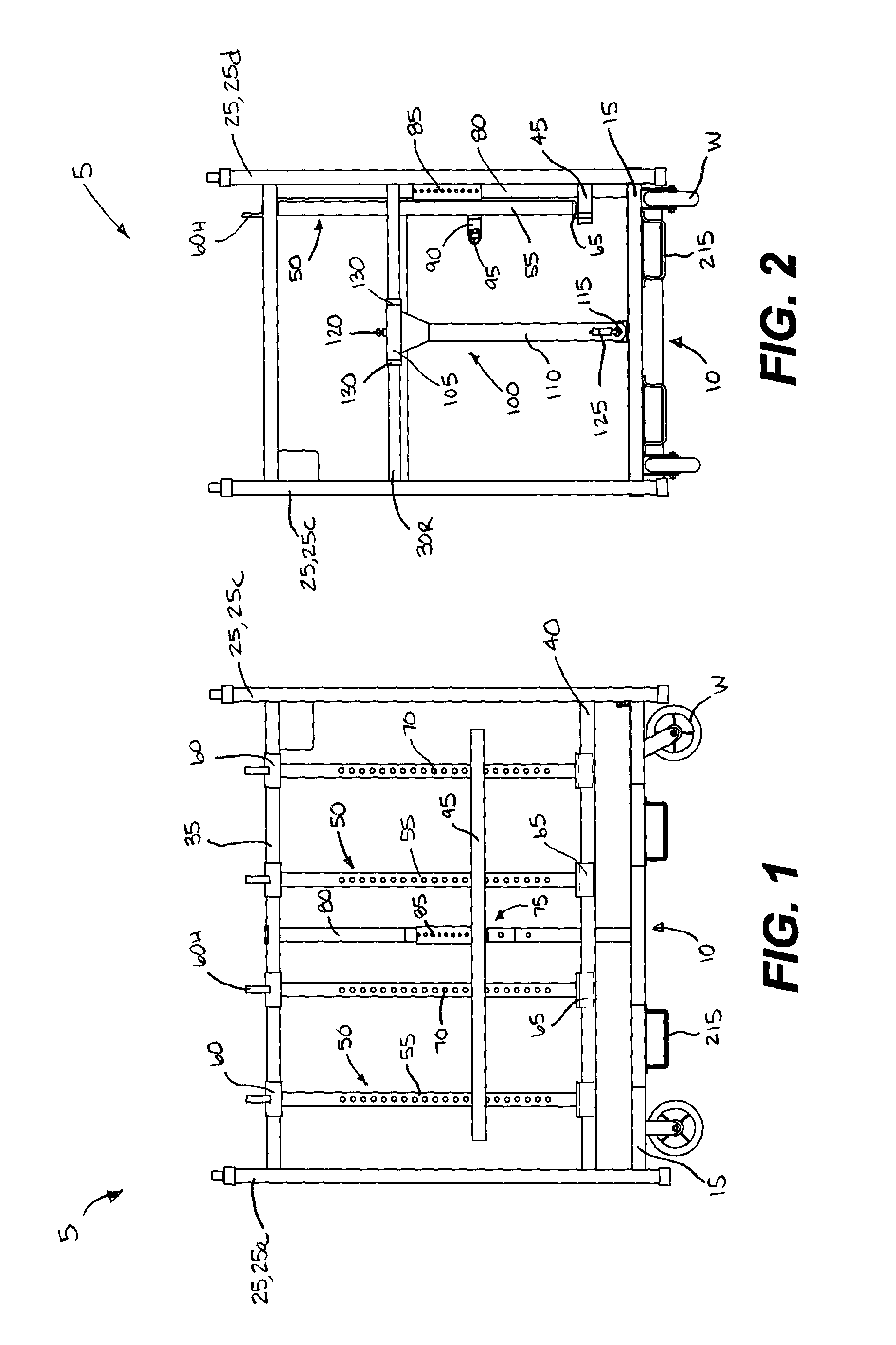
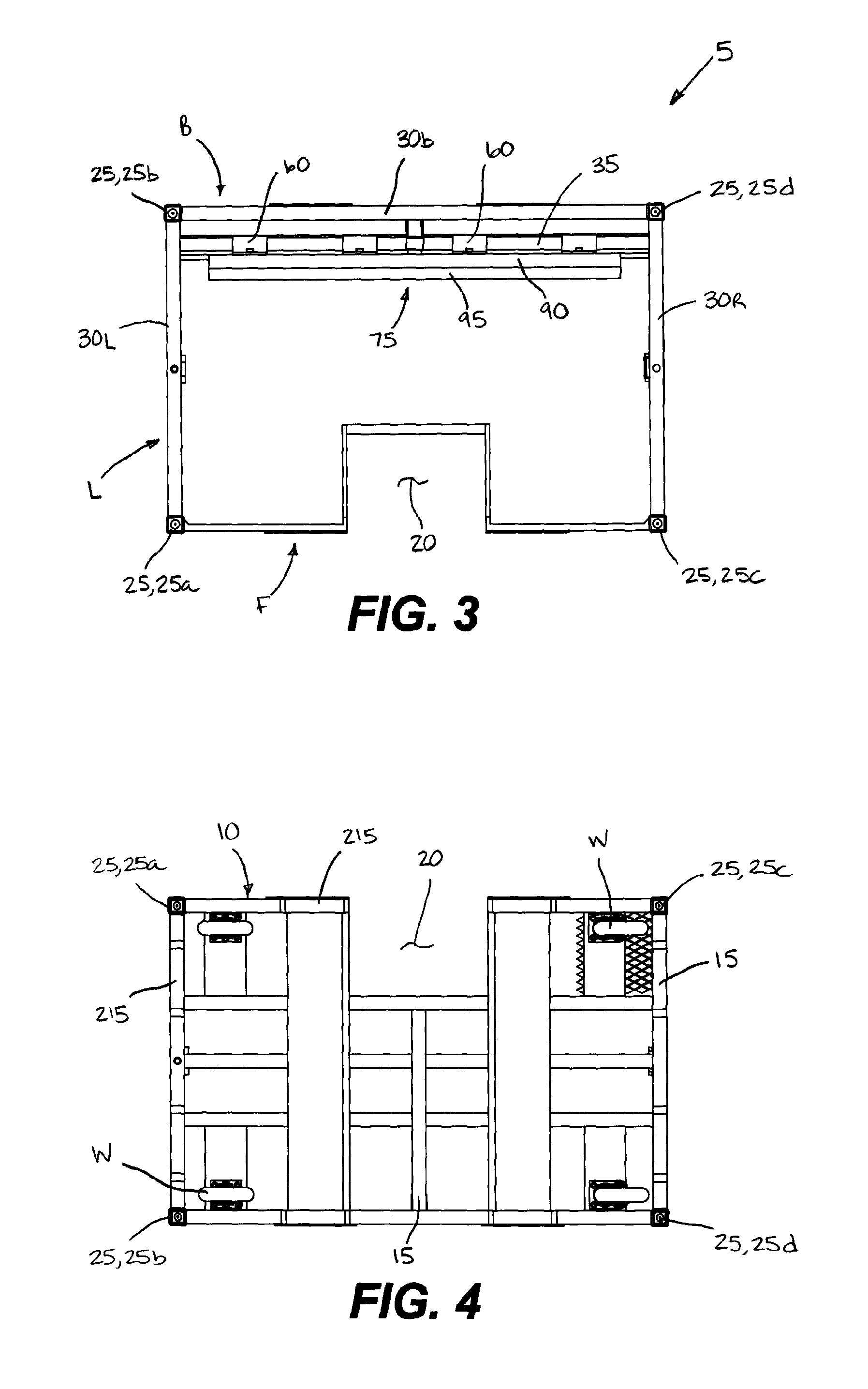
[0031]One exemplary embodiment of an adjustable parts storage rack 5 (“parts storage rack” or “storage rack”) of the present invention is depicted in FIGS. 1-4. As shown, this particular embodiment of the storage rack 5 is comprised of a substantially open framework. Preferably, the framework is constructed of a number of tubular members, although other materials may be substituted. The tubular members may be of square, rectangular, circular or other cross-sectional shape. In other embodiments, the open frameworks of this storage rack 5 may be replaced with substantially solid walls.

[0032]More particularly, the storage rack 5 includes a substantially horizontally-oriented base 10 having a number of interconnected and welded base frame members 15. In this particular embodiment, the base frame members 15 are constructed from square steel tubing, although one skilled in the art would clearly realize that the use of other materials is also possible. Wheels W are preferably, but not nec...


PUM


Abstract

A latching mechanism capable of providing clamped retention to a vertical member, and a repositionable part support device and part support assembly employing said latching mechanism. The latching mechanism includes an enclosure having an open interior for receiving a vertical member and a pivotal handle that can be used to move a clamping roller out of contact with the vertical member during repositioning. A spring may be provided for otherwise biasing the clamping roller toward the vertical member. A support pin is located within the interior of the enclosure to engage a pin-receiving hole in the vertical member. The repositionable part support device and part support assembly may have a part support member that is affixed to and extends from said latching mechanism enclosure.

Description

CROSS-REFERENCE TO RELATED APPLICATIONS[0001]This application is a divisional of U.S. patent application Ser. No. 11 / 859,693, filed Sep. 21, 2007, which is hereby incorporated by reference.BACKGROUND OF THE INVENTIVE FIELD[0002]The present invention is directed to a rack for temporarily storing and transporting parts, such as automotive body panels. More particularly, the present invention is directed to such a rack that is adjustable for use with parts of varying size and or shape.[0003]Part storage racks of various types and designs would be well known to those skilled in the art. Such racks may include individual shelves or compartments on / within which parts are stored. Other similar racks may include various styles of parts hangers that permit parts to be suspended within the confines of the rack frame. These racks are generally employed to store parts on a temporary basis, such as until they are needed in an associated manufacturing process.[0004]Certain embodiments of such rac...

Claims


Application Information

Patent Timeline
Patent Type & Authority Applications(United States)
IPC IPC(8): F16D1/10
CPCB62B2206/06Y10T403/60B65D2519/00024B65D2519/00059B65D2519/00164B65D2519/00233B65D2519/00273B65D2519/00293B65D2519/00323B65D2519/00338B65D2519/00502B65D2519/00532B65D2519/00562B65D2519/00616B65D2519/00666B65D2519/00701B65D2519/00781B65D2519/00805B65D2519/0081B65D2585/6887B62B3/005B62B3/006B65D19/08
Inventor SANDUSKY, JOHNBOLLACK, KEN
Owner HONDA MOTOR CO LTD
Why Eureka
Try Eureka