
Electrodeless Plasma Lamp Array

a technology of plasma lamp array and electrode, which is applied in the direction of energy-saving lighting, gaseous cathodes, sustainable buildings, etc., can solve the problems of limited lifetime, deterioration of electrodes, and the reliability of magnetrons in solid-state power amplifiers, so as to improve heat transfer characteristics, less power, and long life

Inactive Publication Date: 2011-08-25
TOPANGA USA
View PDF17 Cites 9 Cited by
  • Summary
  • Abstract
  • Description
  • Claims
  • Application Information

AI Technical Summary

Benefits of technology

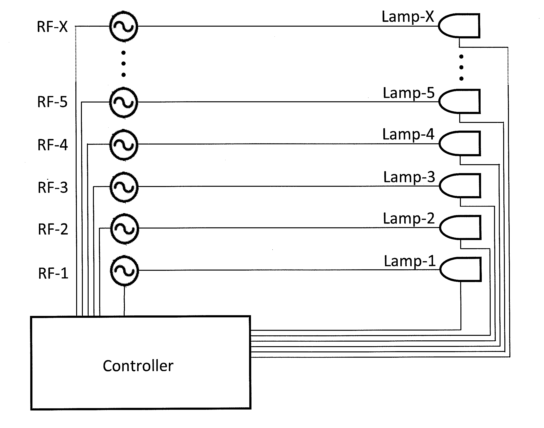
"The present invention provides devices and methods for generating electromagnetic radiation using electrodeless plasma lamps without the use of electrodes. The lamps are controlled by a microcontroller that adjusts the RF power delivered to each lamp, allowing for the control of the intensity and distribution of the output electromagnetic radiation. The lamps can be powered by individual RF sources or a single RF source. The invention can be used in various applications such as large scale thermal and lighting, security, parking lots, military / defense, streets, buildings, and more. The invention also provides an array of electrodeless plasma lamps with a heat exchanger for improved heat transfer characteristics. The lamps can be coupled with an air flow system or a movable array for further improved heat transfer and lighting control. The invention allows for the control of color temperature and the ability to adjust the illumination pattern over a large surface area."

Problems solved by technology

This arrangement, however, suffers from deterioration of the electrodes, and therefore a limited lifetime.
While microwave sources such magnetron are available with RF powers exceeding 1000 W in a compact form factor, magnetrons do not have the reliability of solid-state power amplifiers.
Although it may be possible to achieve higher RF output power from solid-state power amplifiers by combining a number of them, it can result in RF losses through the combiner and impact the overall efficiency of the RF source.
Use of a larger bulb also improves coupling RF energy to the bulb at lower operating frequencies, but it is difficult to optimize the performance of the system for best efficiency of the power amplifier and optimum coupling to the bulb.
Furthermore in some applications it is difficult, if not impossible, to achieve uniform electromagnetic distribution from a large single bulb.
Furthermore the power supplies required for some high lumens / electromagnetic radiation applications are bulky and inefficient.

Method used


Image

  • Electrodeless Plasma Lamp Array
  • Electrodeless Plasma Lamp Array
  • Electrodeless Plasma Lamp Array

Examples


Embodiment Construction

[0036]This invention provides an array of electrodeless plasma lamps to generate higher intensity light (or electromagnetic radiation) distribution, or a particular light (or electromagnetic radiation) distribution, such as a uniform light distribution as well as a method to vary the color temperature and color rendering index of lighting. Such array of electrodeless plasma lamps can be applied to applications such as stadiums, security, parking lots, military and defense, streets, large and small buildings, vehicle headlamps, aircraft landing, bridges, warehouses, UV water treatment, UV epoxy curing, semiconductor processing, annealing, heating, agriculture, architectural lighting, stage lighting, medical illumination, projectors and displays, as well as similar applications.

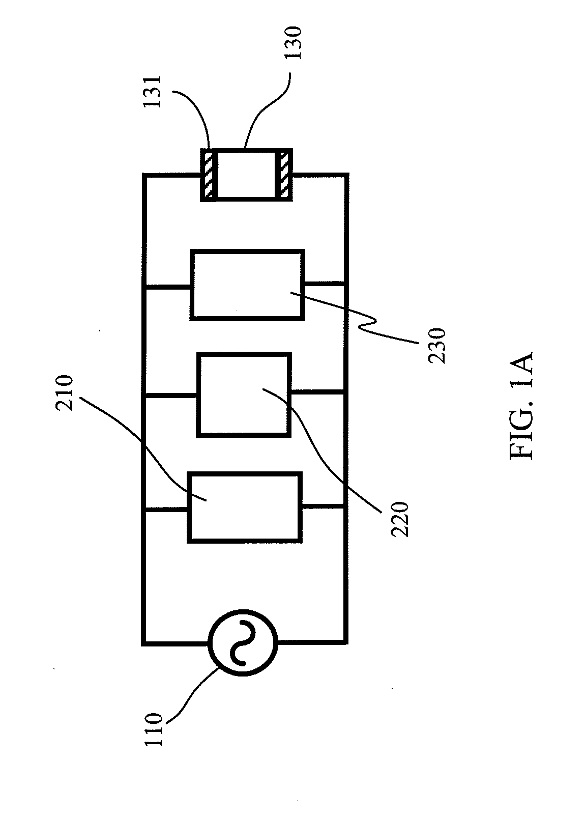
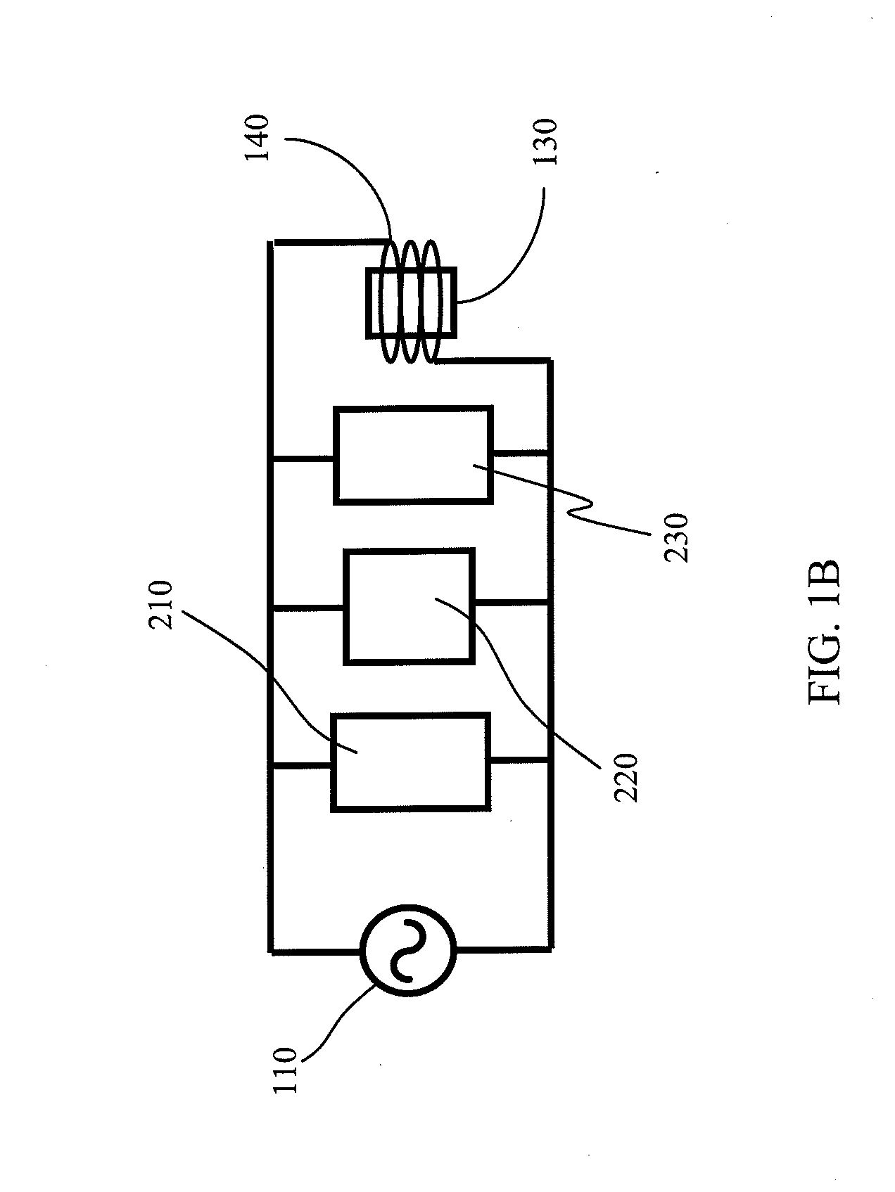
[0037]FIGS. 1 and 2 illustrate electrodeless plasma lamps which can be used in the arrays of the present invention. FIG. 1A illustrates a general schematic for efficient energy transfer from RF source 110 to ga...


PUM


Abstract

An electrodeless plasma lamp array structure uses multiple plasma lamps to produce large amounts of electromagnetic radiation (visible, IR, UV, or a combination of visible, IR, and UV). An M by N array configuration is powered by either a single RF power source or multiple RF power sources. The array incorporates controllers to adjust the power delivered from the RF power source to each lamp within the array. By adjusting the delivered RF power, the intensity of electromagnetic radiation that is emitted from each lamp is controlled independently allowing for the creation of an array of lamps that emit electromagnetic radiation of varying intensity levels at different places within the array. Using lamps with different color temperatures as part of the array allows the color temperature and the color rendering index of the illumination to achieve different lighting conditions.

Description

CROSS-REFERENCE TO RELATED APPLICATION[0001]The present invention claims priority to U.S. Provisional Patent Application No. 61 / 187,209, filed Jun. 15, 2009, which is incorporated by reference herein for all purposes.BACKGROUND OF THE INVENTION[0002]This invention is directed to devices and methods for generating electromagnetic radiation, including visible, ultra-violet, and infrared, with electrodeless plasma lamps. The present invention provides plasma lamps driven by a radio-frequency source without the use of electrodes inside a gas-filled vessel (bulb). More particularly the invention involves the creation of an array of electrodeless plasma lamps. Such array of electrodeless plasma lamps can be applied to applications such as stadiums, security, parking lots, military and defense, streets, large and small buildings, vehicle headlamps, aircraft landing, bridges, warehouses, UV water treatment, UV epoxy curing, semiconductor processing, annealing, heating, agriculture, architec...

Claims


Application Information

Patent Timeline
Patent Type & Authority Applications(United States)
IPC IPC(8): H05B41/24H01J7/24H05B41/36
CPCH01J65/044Y02B20/22H05B41/39H05B41/2806Y02B20/00
Inventor DOUGHTY, DOUGLAS A.MATLOUBIAN, MEHRANESPIAU, FREDERICK M.
Owner TOPANGA USA
Learn More