
Non-tracking solar collector device

Inactive Publication Date: 2011-08-25
KLOBEN S A S DI TURCO ADELINO E C
View PDF38 Cites 44 Cited by
  • Summary
  • Abstract
  • Description
  • Claims
  • Application Information

AI Technical Summary

Benefits of technology

[0023]The aim of the present invention is to provide a non-tracking solar collector device that permits to prevent overheating of the absorber element more efficiently in respect of the known devices, particularly in the case of reflector elements having a considerable length and weight.
[0024]Within this aim, another object of the present invention is to provide a non-tracking solar collector device that requires a relatively small applied force and energy to obscure quickly the absorber element so as to prevent its overheating.
[0025]Another object of the present invention is to efficiently convey the sunlight onto the absorber element during the various stages of the day, in order to maximize the amount of energy captured.
[0026]Within the scope of such technical aim, another object of the present invention is to cater for the above aims with a simple structure, of relatively practical implementation, safe to use and with effective operation, as well as having a relative low cost.

Problems solved by technology

The rotating blade design is difficult to implement for a parabolic or compound parabolic trough reflector due to the elongated reflector and absorber element, the close proximity of the absorber element to the reflector surface in most non-tracking collector designs, and the wide range of directions for radiation incident on the absorber element after reflection from a trough reflector.
This translation mechanism is not specifically designed to prevent overheating of the absorber elements.
Indeed this translation mechanism, involving translation of the entire reflector system, is very complex and in the case of large and elongated reflector elements does not quickly and efficiently control the sunlight intensity incident on the absorber element.
Moreover, this translation mechanism is not suitable when the fixed absorber element is disposed between the reflector elements because translation of the reflector will be obstructed by the absorber element.
Moreover, this translation mechanism requests a relatively large amount of applied force and energy for translating the reflector elements.
None of the collectors with rotatable reflector elements are designed specifically to avoid overheating of the absorber element and require manual intervention to enclose the absorber element.
Moreover, the known collector devices utilize rotation of substantially the entire area of reflector elements, that results in a complex drive mechanism and that is non-efficient in avoiding overheating of the absorber element.
More particularly, in the case of non-portable collectors it is not possible to incorporate in an efficient way a drive mechanism for reflector elements having a large and elongated shape due to the relatively large force and energy required to quickly move the entire area of reflector elements that have considerable length and weight.
This device however is also susceptible of improvements.
So, the structure of the non-tracking solar collector devices already known and the conformation of their reflector elements doesn't efficiently prevent overheating of the absorber element disposed between the reflector elements themselves.

Method used


Image

  • Non-tracking solar collector device
  • Non-tracking solar collector device
  • Non-tracking solar collector device

Examples


Embodiment Construction

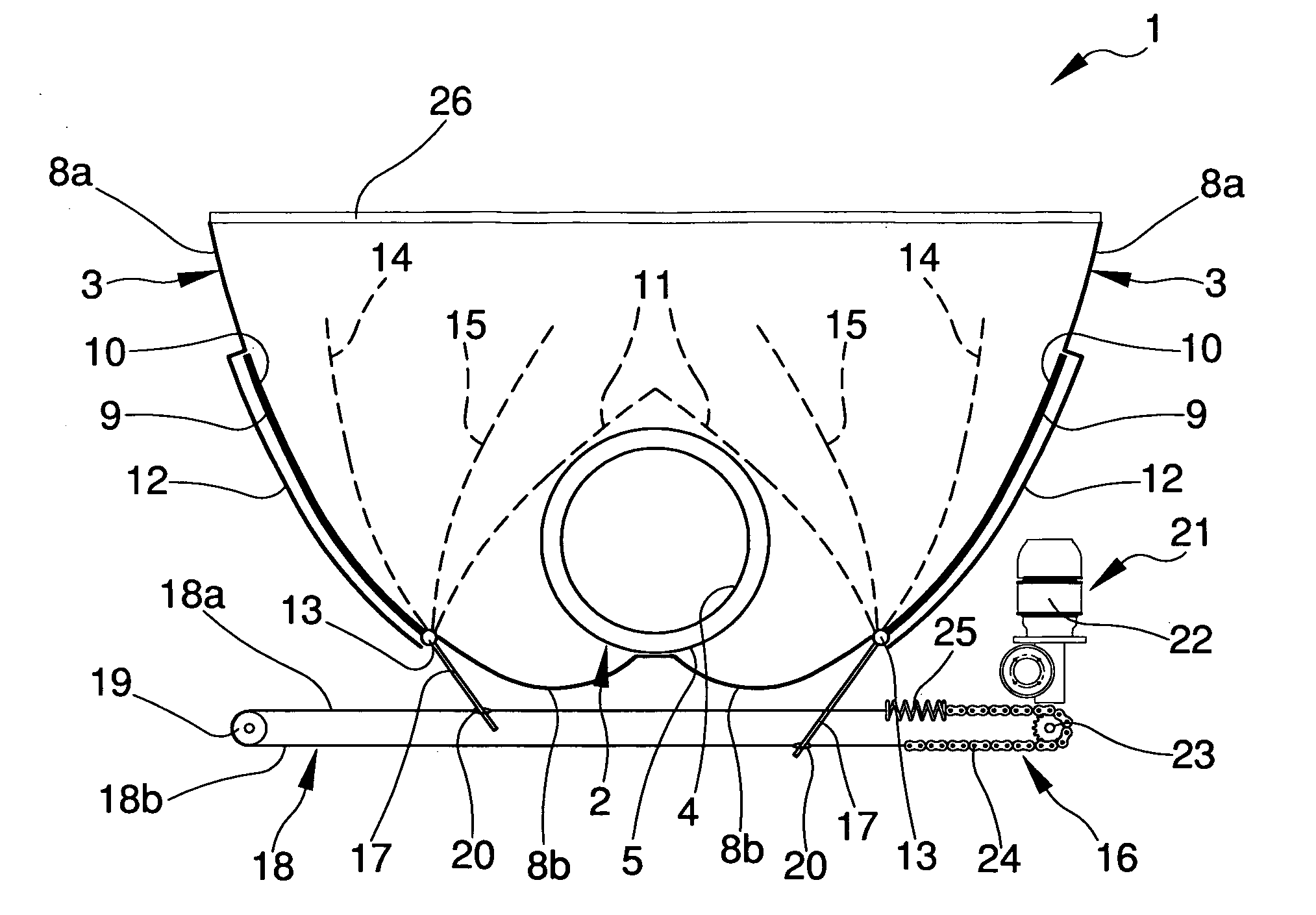
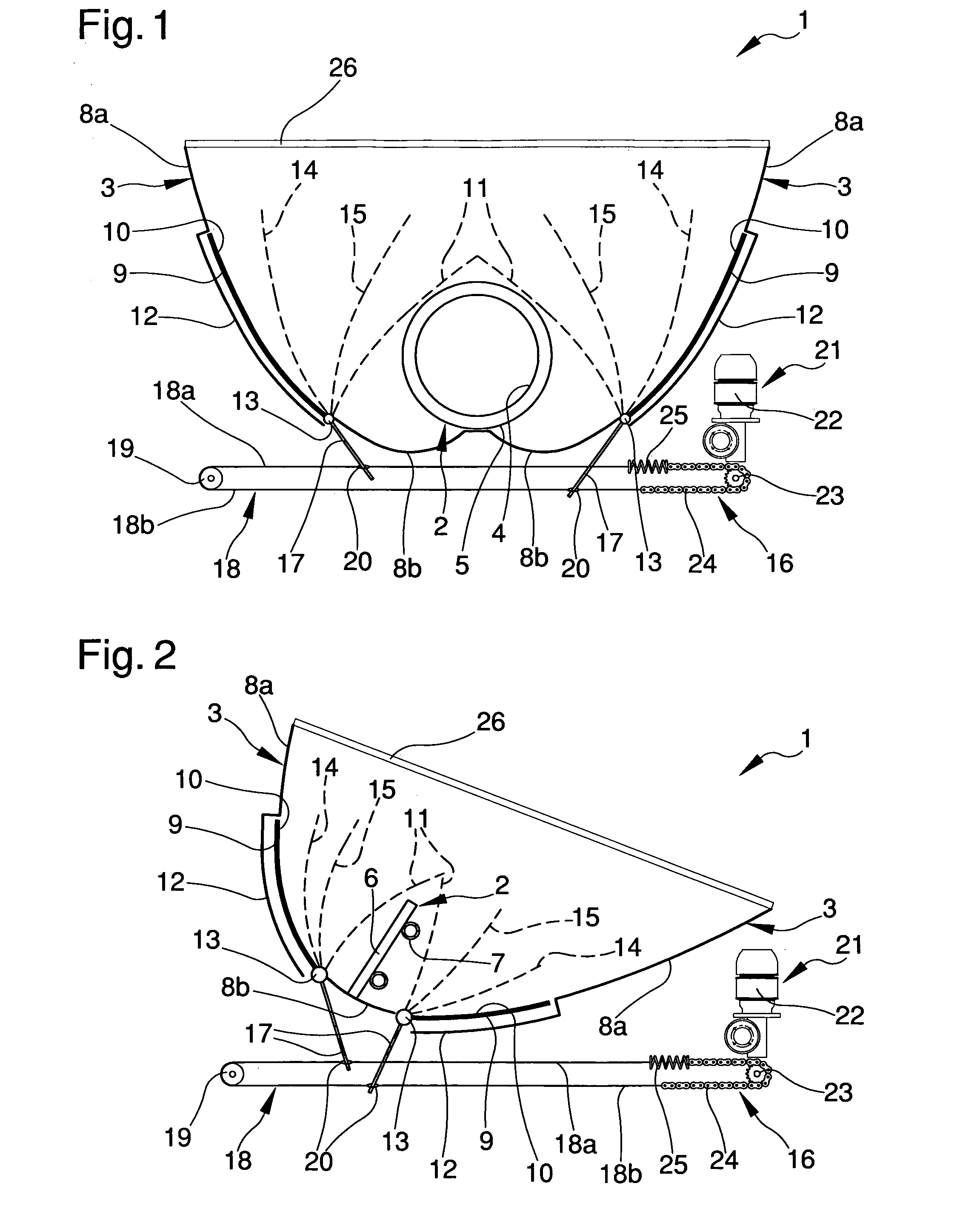
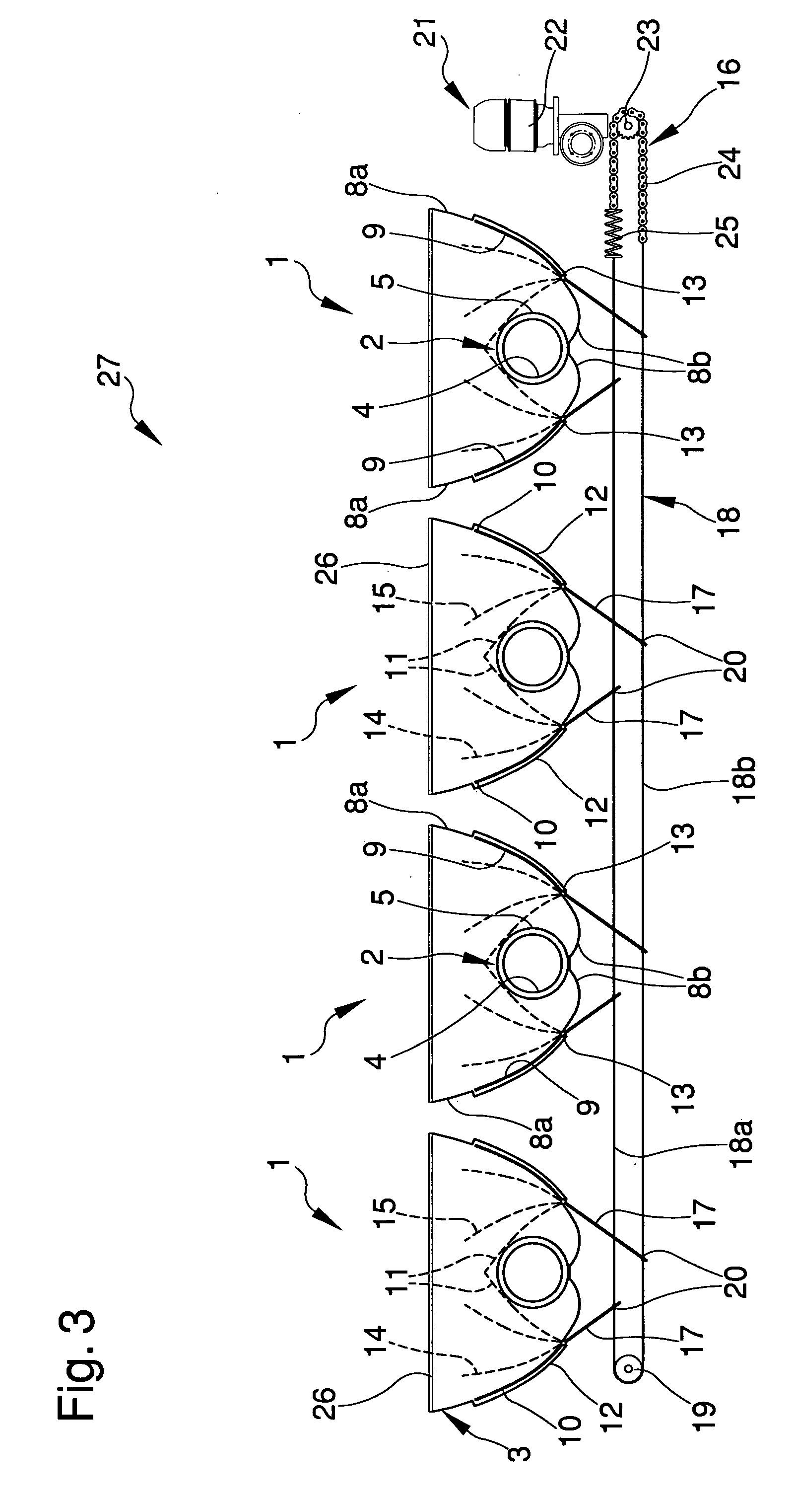
[0035]With particular reference to such figures, globally indicated by 1 is a non-tracking solar collector device.

[0036]The device 1 comprises at least an absorber element 2 and at least a couple of reflector elements 3 disposed on opposite sides of the absorber element 2 for conveying the solar radiation onto the absorber element itself.

[0037]In the example represented in FIG. 1, the absorber element 2 is an example of a tubular absorber of the evacuated glass tubular collector type for heat production and comprises an elongated absorber tube 4 with glass envelope 5 which extends longitudinally along the entire length of the device 1.

[0038]In the example of FIG. 2, the absorber element 2 is constituted by a metal plate 6 with attached metal tubes 7 for heat production.

[0039]In other embodiments (not shown), the absorber element 2 may be constituted by an array of solar photovoltaic cells disposed on an elongated metal strip for electricity production or by a metal plate with attach...


PUM


Abstract

Non-tracking solar collector device (1) comprising at least an absorber element (2), at least a couple of reflector elements (3) disposed on opposite sides of the absorber element (2) for conveying the solar radiation onto the absorber element itself and said reflector elements (3) comprising at least one fixed portion (8a,8b) and at least one rotating portion (9); the rotating portions (9) being movable between at least a first extreme position (10), in which the rotating portions are moved away from each other and the entire surface of said reflector elements (3) is substantially continuous, and a second extreme position (11), in which the rotating portions are moved close to each other in order to substantially obscure said absorber element (2).

Description

CROSS-REFERENCE TO RELATED APPLICATIONS[0001]This application claims the benefit of PCT International Patent Application No. PCT / 1B2009 / 006455, filed Aug. 5, 2009, and Australian Patent Application No. 2008904860, filed Sep. 18, 2008, in the Australian Patent Office, the disclosures of which are incorporated herein by reference.BACKGROUND OF THE INVENTION[0002]1. Field of the Invention[0003]The present invention relates to a non-tracking solar collector device.[0004]2. Description of the Related Art[0005]Solar radiation collection devices incorporating reflector elements for focusing incident radiation onto an absorber element are well known. The reflector elements may consist of a large aperture elongated parabolic trough which moves to track the sun and thereby maintain the focusing of sunlight onto an absorber element. In the case where smaller aperture reflector troughs are used, a non-tracking stationary reflector may be used. Such reflectors are usually of the parabolic concen...

Claims


Application Information

Patent Timeline
IPC IPC(8): F24J2/04F24J2/40F24J2/10F24J2/54F24S23/70F24S23/74
CPCF24J2/055F24J2/1047F24J2/265F24J2/4623F24J2/5403H01L31/0547F24J2002/5468Y02E10/44Y02E10/47Y02E10/52F24J2002/5458F24S10/45F24S10/753F24S23/80F24S30/42F24S40/52F24S50/00F24S50/40F24S2030/133F24S2030/136
Inventor HARDING, GEOFFREY LESTER
Owner KLOBEN S A S DI TURCO ADELINO E C
Learn More