
Novel enhanced methods for mimicking human gait with prosthetic knee devices

Active Publication Date: 2011-08-18
PROTEOR USA LLC
View PDF18 Cites 42 Cited by
  • Summary
  • Abstract
  • Description
  • Claims
  • Application Information

AI Technical Summary

Benefits of technology

[0010]The present invention relates to a prosthetic device including a prosthetic joint which more accurately transitions between a loose mode and a stiff mode to thereby more accurately mimic a human gait. The prosthetic joint can include a state controller, a sensor system consisting of one or more sensors, a memory, and a controllable actuator system. The state controller can utilize the sensor system to detect prosthetic joint movement data, which is compared with expected normal prosthetic joint movement data to decide the state of the control system. When the prosthetic joint is in a Setup Swing Flexion state, the state controller progresses the prosthetic joint through additional states before commanding the actuator to place the prosthetic joint in a patricular mode. This prevents the prosthetic joint from entering a mode prematurely. This can prevent for instance the amputee placing his weight on the prosthetic device and losing his balance. It can also prevent the amputee from feeling the prosthetic joint change resistance inappropriately and the subsequent undesirable sensation.
[0011]The prosthetic joint can also be part of a prosthetic joint system which also additionally includes an optimization unit. The optimization unit can generate a plurality of data files containing prosthetic joint movement data corresponding to an amputee walking at various speeds without stumbling. By iteratively analyzing the prosthetic joint movement data, the optimization unit can adjust the prosthetic joint movement decision values to ensure that the prosthetic joint does not prematurely enter a stumble recovery state. This ensures that the prosthetic joint does not prematurely enter high resistance mode due to a perceived stumble when the amputee is not actually stumbling. Optimizing the prosthetic joint movement decision values can also reduce instances where the prosthetic device unnecessarily transitions to the incorrect mode. Furthermore, it also allows for greater accuracy in transitioning into a high resistance mode when the amputee has an unexpected gait deviation. This can provide better support for the amputee. The optimization unit also allows for a simplistic optimization of the prosthetic joint movement decision values, reducing setup costs for the prosthetic device.

Problems solved by technology

However, modern, computer-controlled prosthetic devices have some drawbacks, which may not allow amputees to take full advantage of all of their features.
However, the events that trigger the transition from stiff mode to loose mode, or vice versa, can occur at times when a transition is not desirable and thereby cause discomfort to the amputee.
For example, if the prosthetic joint is loose at the wrong time, the amputee could place weight on the prosthetic device and possibly lose his or her balance, or the amputee can feel the prosthetic joint loosen creating an undesirable sensation.
However, if the prosthetic joint is stiff at the wrong time, the amputee may walk with an undesirable gait.
Given that the modern, computer-controlled prosthetic devices are designed to more accurately mimic a human gait and thus provide vastly more functionality than a crude peg, these drawbacks defeat the purpose of the modern, computer-controlled prosthetic devices and can limit their value.
However, as the modern, computer-controlled prosthetic device becomes more sophisticated, the number of variables begins to increase drastically.
Manually adjusting each variable to tune the modern, computer-controlled prosthetic device becomes laborious, time-consuming, and cost ineffective.

Method used


Image

  • Novel enhanced methods for mimicking human gait with prosthetic knee devices
  • Novel enhanced methods for mimicking human gait with prosthetic knee devices
  • Novel enhanced methods for mimicking human gait with prosthetic knee devices

Examples


Embodiment Construction

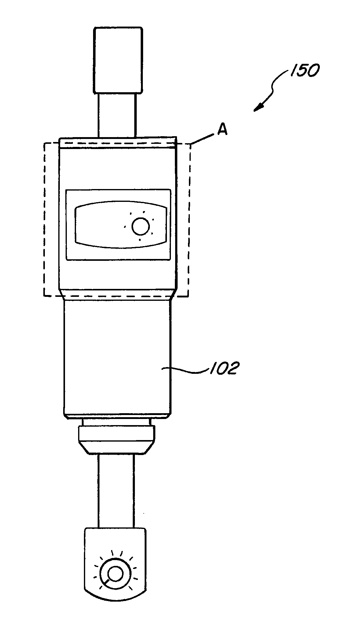
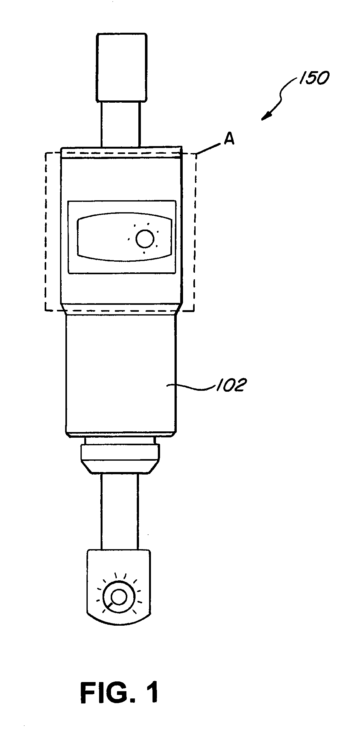
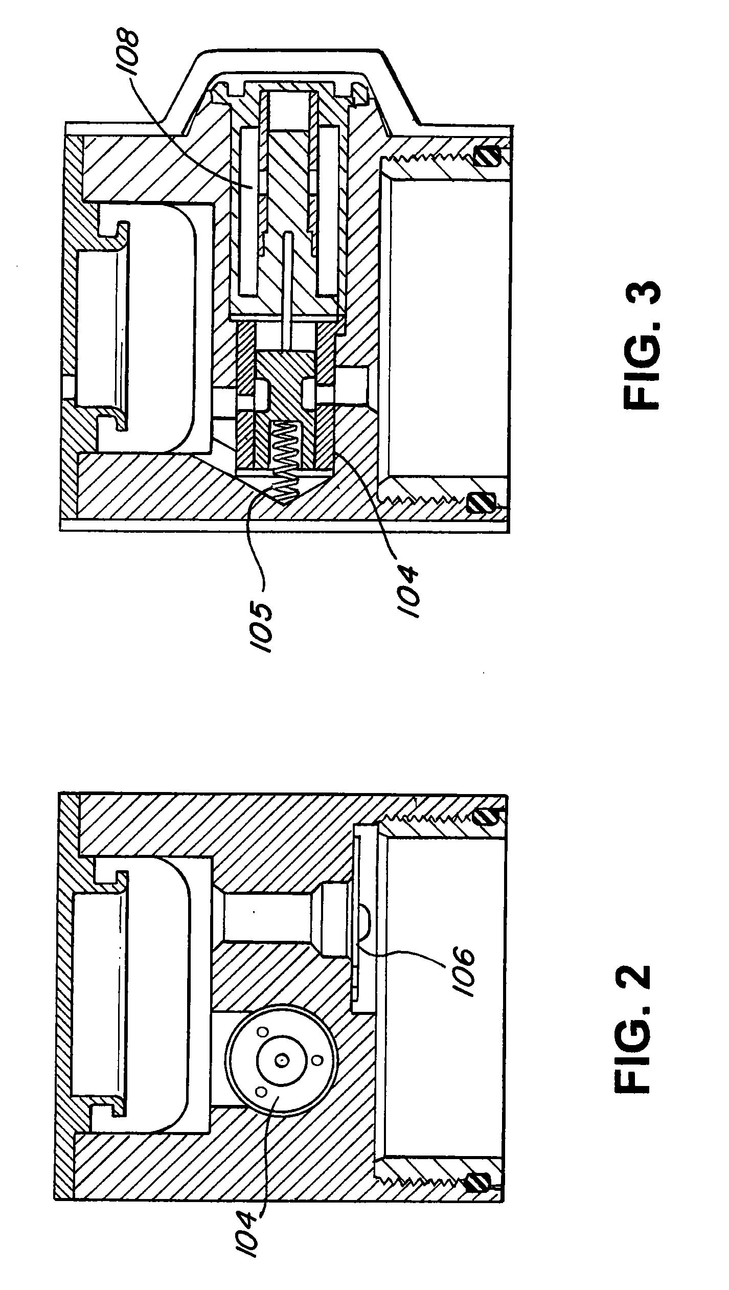
[0036]In one embodiment, the present invention includes, for example, an actuator 150. The actuator 150 can be part of a prosthetic joint, which in turn can be used as part of a prosthetic device. The actuator 150 includes, for example, a hydraulic damping cylinder 102. As seen in FIG. 2 (which is a cross-sectional view of the portion A in FIG. 1, the hydraulic damping cylinder 102 includes a spool valve 104 and reed check valve 106. As seen in FIG. 3, the hydraulic damping cylinder 102 also includes a return spring 105 and a solenoid 108.

[0037]When the solenoid 108 is energized, the solenoid 108 opens the spool valve 104 and permits fluid to flow through the spool valve 104. This reduces the damping of the hydraulic damping cylinder 102 to permit easy bending of the prosthetic joint 100. However, when the solenoid 108 is de-energized, the spool valve 104 can be closed by return spring 105, and no fluid flows through the spool valve 104. This increases the damping of the hydraulic d...


PUM


Abstract

The present invention relates to a prosthetic device including a prosthetic joint which accurately transitions between a loose mode and a stiff mode to more accurately mimic a human gait. The prosthetic joint includes a state controller which utilizes a sensor to detect prosthetic joint movement data, and compares it with prosthetic joint movement decision values to determine when a solenoid should be energized to place the prosthetic joint in the loose mode. An optimization unit connects to the prosthetic joint in a prosthetic joint system. The optimization unit generates a plurality of data files containing prosthetic joint movement data corresponding to an amputee walking without stumbling. By iteratively analyzing the prosthetic joint movement data, the optimization unit adjusts the prosthetic joint movement decision values to ensure that the prosthetic joint does not prematurely enter a stumble recovery state.

Description

CROSS-REFERENCE TO RELATED APPLICATIONS[0001]The present application claims priority from U.S. Provisional Application Ser. No. 61 / 304,345 filed on Feb. 12, 2010 entitled “Novel Enhanced Methods for Mimicking Human Gait With Prosthetic Knee Devices.” This application also claims the benefit of and Paris Convention priority of U.S. Utility patent application Ser. No. 12 / 697,969 filed on Feb. 1, 2010 entitled “Novel Enhanced Methods for Mimicking Human Gait With Prosthetic Knee Devices” and further incorporates by reference U.S. Pat. No. 7,655,050.BACKGROUND[0002]1. Field of the Invention[0003]The present disclosure relates generally to prosthetic devices and, more particularly, to prosthetic devices including a prosthetic joint which more accurately transitions between a loose mode and a stiff mode to thereby more accurately mimic a human gait.[0004]2. Description of the Related Art[0005]Modern, computer-controlled prosthetic devices have many advantages over conventional prosthetic ...

Claims


Application Information

Patent Timeline
IPC IPC(8): A61F2/62
CPCA61B5/1114A61B5/1117A61B5/112A61B5/1123A61F2/64A61B5/4851A61F2002/701A61F2002/704A61F2002/7625A61F2002/7645A61F2/68A61F2/70
Inventor PALMER, MICHAEL L.BISBEE, III, CHARLES R.
Owner PROTEOR USA LLC
Learn More