
Point source transmission and speed-of-sound correction using multi-aperture ultrasound imaging

Active Publication Date: 2011-08-18
MAUI IMAGING
View PDF102 Cites 63 Cited by
  • Summary
  • Abstract
  • Description
  • Claims
  • Application Information

AI Technical Summary

Benefits of technology

[0030]In another embodiment of the multi-aperture ultrasound imaging system, the control system can be coupled to the transmit aperture and the first and second receive apertures, wherein the control system is configured to determine a third time for the waveform to propagate from the first point source to a first pixel location in the target region to the third receiving element, and is configured to determine a fourth time for the waveform to propagate from the first point source to the first pi

Problems solved by technology

This design configuration lies at the heart of one of the most significant limitations in the use of ultrasonic imaging for medical purposes: poor lateral resolution.
Theoretically, the lateral resolution could be improved by increasing the width of the aperture of an ultrasonic probe, but practical problems involved with aperture size increase have kept apertures small.
For scanners intended for abdominal and other use, the limitation on aperture size is less a matter of physical constraints, and more a matter of difficulties in image processing.
The problem is that it is difficult to keep the elements of a large aperture array in phase because the speed of ultrasound transmission varies with the type of tissue between the probe and the area of interest.
When the size of the aperture is increased to improve the lateral resolution, the additional elements of a phased array may be out of phase and may actually degrade the image rather than improving it.

Method used


Image

  • Point source transmission and speed-of-sound correction using multi-aperture ultrasound imaging
  • Point source transmission and speed-of-sound correction using multi-aperture ultrasound imaging
  • Point source transmission and speed-of-sound correction using multi-aperture ultrasound imaging

Examples


Embodiment Construction

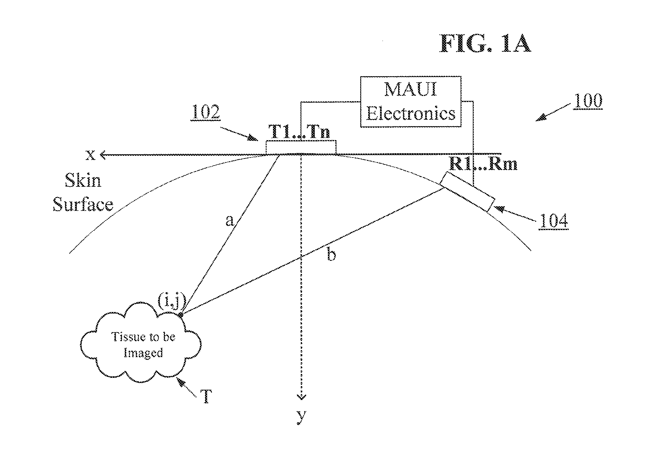
[0040]Greatly improved lateral resolution in ultrasound imaging can be achieved by using multiple separate apertures for transmit and receive functions. Systems and methods herein may provide for both transmit functions from point sources and for compensation for variations in the speed-of-sound of ultrasound pulses traveling through potentially diverse tissue types along a path between a transmit aperture and one or more receive apertures. Such speed-of-sound compensation may be performed by a combination of image comparison techniques (e.g., cross-correlation), and the coherent and / or incoherent averaging of a plurality of received image frames.

[0041]As used herein the terms “ultrasound transducer” and “transducer” may carry their ordinary meanings as understood by those skilled in the art of ultrasound imaging technologies, and may refer without limitation to any single component capable of converting an electrical signal into an ultrasonic signal and / or vice versa. For example, ...


PUM


Abstract

A Multiple Aperture Ultrasound Imaging system and methods of use are provided with any number of features. In some embodiments, a multi-aperture ultrasound imaging system is configured to transmit and receive ultrasound energy to and from separate physical ultrasound apertures. In some embodiments, a transmit aperture of a multi-aperture ultrasound imaging system is configured to transmit an omni-directional unfocused ultrasound waveform approximating a first point source through a target region. In some embodiments, the ultrasound energy is received with a single receiving aperture. In other embodiments, the ultrasound energy is received with multiple receiving apertures. Algorithms are described that can combine echoes received by one or more receiving apertures to form high resolution ultrasound images. Additional algorithms can solve for variations in tissue speed of sound, thus allowing the ultrasound system to be used virtually anywhere in or on the body.

Description

CROSS REFERENCE TO RELATED APPLICATIONS[0001]This application claims the benefit of U.S. Provisional Patent Application No. 61 / 305,784, filed on Feb. 18, 2010, titled “Alternative Method for Medical Multi-Aperture Ultrasound Imaging”.[0002]This application is also related to U.S. patent application Ser. No. 11 / 865,501, filed Oct. 1, 2007, titled “Method and Apparatus to Produce Ultrasonic Images Using Multiple Apertures”, and to U.S. patent application Ser. No. 11 / 532,013, filed Sep. 14, 2006, titled “Method and Apparatus to Visualize the Coronary Arteries Using Ultrasound”; all of which are herein incorporated by reference in their entirety.INCORPORATION BY REFERENCE[0003]All publications, including patents and patent applications, mentioned in this specification are herein incorporated by reference in their entirety to the same extent as if each individual publication was specifically and individually indicated to be incorporated by reference.BACKGROUND OF THE INVENTION[0004]In co...

Claims


Application Information

Patent Timeline
IPC IPC(8): A61B8/14
CPCG01S7/52049G01S15/8913G01S15/8927G01S15/8961A61B8/5207G01S15/8993A61B8/4477G01S15/8997A61B8/14G01S15/8977A61B8/4455A61B8/145A61B8/4483A61B8/5246A61B8/5269A61B8/4444A61B8/463
Inventor SPECHT, DONALD F.BREWER, KENNETH D.
Owner MAUI IMAGING
Learn More