
Automatic air duct register

a technology of air duct register and automatic measurement, which is applied in the direction of lighting and heating apparatus, ventilation systems, heating types, etc., can solve the problems of unoccupied rooms, uncomfortable heating or cold in other rooms of the building, and significant temperature differences in various rooms away from the thermostat, so as to save energy and accurately measure the temperature in a room. , the effect of saving energy

Inactive Publication Date: 2011-08-18
DROPMANN HANS
View PDF9 Cites 61 Cited by
  • Summary
  • Abstract
  • Description
  • Claims
  • Application Information

AI Technical Summary

Benefits of technology

[0009]In one embodiment, the register may be opened or closed, responsive to an electronic timer or clock included within the register system. The timer or clock may be programmed, so that the register is closed at certain predetermined times. Thus, energy is saved, as the room is effectively cut off from the HVAC system when the register is closed. The airflow from the central furnace or air conditioning system that had been intended for this room may service other rooms within the building or home.
[0010]In another embodiment, the register may be opened or closed, responsive to an occupancy sensor determining when the room serviced by the register system is unoccupied. Thus, energy is saved, as the room is effectively cut off from the HVAC system when the register is closed. The airflow from the central furnace or air conditioning system that had been intended for this room may service other rooms within the building or home.
[0011]In another embodiment, the register system may include an infrared temperature sensor, designed to accurately measure the temperature in a room, the register's airflow controlled in accordance with the comparison of a measured temperature and a desired temperature setpoint. Thus, the temperature of the room is locally controlled with the register system, reducing temperature fluctuations and increasing comfort.
[0012]In another embodiment, the register system is part of a control network, wherein the network communicates with the register system. The register system accepts commands to set the timer or clock, or set the desired temperature setpoint. The register system may send information about the temperature measured in the room, or other information about the register system. Thus, the register system may be operated remotely with network control, obviating the need to program the register system on-site, improving the convenience of the system.
[0013]In another embodiment, the register system is self-powered, utilizing power generated from the flow of air through the register. The power may be derived utilizing a turbine connected to an electric generator. The power may be stored in a large value, low voltage capacitor (supercapacitor) or rechargeable battery, thus eliminating the need to replace batteries in the system.

Problems solved by technology

It is commonly known that the drawback to single-zoned HVAC systems is that the temperature in various rooms away from the thermostat can vary significantly from the thermostat's temperature setting, since the temperature in these rooms does not influence the thermostat to affect the cycling of the furnace or air conditioning system.
Thus, while the thermostat maintains the temperature of the room in which it is installed, other rooms in the building may become uncomfortably hot or cold.
Further, some rooms in the building may not be occupied for certain periods.
In single-zoned HVAC systems, adjusting the thermostat's temperature setting can reduce the amount of heating or cooling, but affects the temperature in the entire building rather than individual rooms.
If fitted with louvers that can be opened and closed mechanically, such as with lever 110 shown in FIG. 1, individual registers in the rooms may be manually closed off during unoccupied periods, but this is inconvenient, requiring the occupant to operate the lever manually at certain times.
The main drawback of multiple-zoned HVAC systems is cost.
The material cost of in-line dampers, power transformers used to power the dampers, control electronics, wiring, and additional thermostats can be substantial.
However, the installation cost may exceed the material cost, especially if the zones are being added to an existing HVAC system; in this case, ducts must be retrofitted inside crawlspaces, walls and ceilings, and wiring routed to a controller located near the furnace or air conditioning unit.
The installation work is typically done by a contractor specializing in HVAC work, resulting in high skilled labor costs.

Method used


Image

  • Automatic air duct register
  • Automatic air duct register
  • Automatic air duct register

Examples


Embodiment Construction

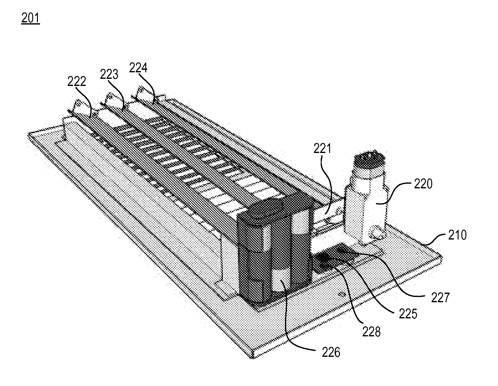
[0023]The Figures (FIG.) and the following description relate to preferred embodiments of the present invention by way of illustration only. It should be noted that from the following discussion, alternative embodiments of the structures and methods disclosed herein will be readily recognized as viable alternatives that may be employed without departing from the principles of the claimed invention.

[0024]Reference will now be made to several embodiments of the present invention(s), examples of which are illustrated in the accompanying figures. Wherever practicable similar or like reference numbers may be used in the figures and may indicate similar or like functionality. The figures depict embodiments of the present invention for purposes of illustration only. One skilled in the art will readily recognize from the following description that alternative embodiments of the structures and methods illustrated herein may be employed without departing from the principles of the invention d...


PUM


Abstract

An automatic air duct register system operating within an HVAC system comprises an automatically controlled register. The register includes louvers which are electromechanically adjusted in order to control the airflow through the register. The register may be opened or closed, responsive to a programmable electronic timer or clock, an occupancy sensor, or in response to a measured temperature. The register system may be part of a control network, wherein the network communicates programming information to the register system, and wherein the network reads information from the register system. The register system may be self-powered, utilizing an electrical generator powered from airflow from the duct attached to the register system.

Description

BACKGROUND OF THE INVENTION[0001]The present invention relates to a system comprising automatically controlled air duct registers in a heating / ventilation / air conditioning (HVAC) system.[0002]As is well known, buildings, including homes and businesses, are typically equipped with a centrally-controlled HVAC system. A common type of HVAC system is known as a forced-air system, and comprises a central furnace (for heating) or air conditioning system (for cooling) to provide heated or cooled air, respectively, to a network of air ducts throughout the building. The air ducts deliver the heated or cooled air to various rooms within the building through registers, which are affixed to the terminus of the various ducts where they enter the rooms.[0003]Often, HVAC systems are equipped with a single thermostat which controls the temperature in the building according to the thermostat's temperature setting. The thermostat is installed in a central location, and turns on the furnace or air con...

Claims


Application Information

Patent Timeline
IPC IPC(8): F24F7/00
CPCF24F11/0012F24F11/0034F24F2011/0073F24F2011/0068F24F13/082F24F11/30F24F2110/10F24F2120/10F24F11/56F24F11/61F24F11/57F24F11/58F24F11/74
Inventor DROPMANN, HANS
Owner DROPMANN HANS
Learn More