Monitoring and Recording Device for Clean-In-Place System

a technology of recording device and clean-in-place system, which is applied in the direction of cleaning process and equipment, packaging, chemistry apparatus and processes, etc., can solve the problems of conductivity probe, false indication of water conductivity, and difficult cleaning of tanks, pumps, valves, and piping

Inactive Publication Date: 2011-08-18
KENOWSKI ANDY +1
View PDF45 Cites 51 Cited by
  • Summary
  • Abstract
  • Description
  • Claims
  • Application Information

AI Technical Summary

Benefits of technology

The data in the data table can identify certain malfunctions in the clean-in-place system 212 to help keep the clean-in-place system 212 functioning properly. The controller 78 executes a stored program to provide an alarm signal if the air flow sensor 148 outputs a signal indicating air flow and the valve position sensor 134 outputs a signal indicating that the valve 20 is in the closed position or has not rea...

Problems solved by technology

However, the tanks, pumps, valves, and piping can be difficult to clean because the various components may be difficult to access and disassemble for cleaning.
However, conductivity probes can be fouled over time by chemical build-up thereby providing false indications of the water conductivity.
Also, conductivity probes can fail thereby providing no indication of the water conductivity.
Systems with fouled or nonfunctioning probes lead to overuse of a cleaning chemical.
However, these devices may not be suitable for diagnosing all clean-in-place system fluid flow problems such as non-operational valves.
Additionally, these devices are generally limited in the number and type of sensors that can be used in a single system.

Method used


Image

  • Monitoring and Recording Device for Clean-In-Place System
  • Monitoring and Recording Device for Clean-In-Place System
  • Monitoring and Recording Device for Clean-In-Place System

Examples


second embodiment

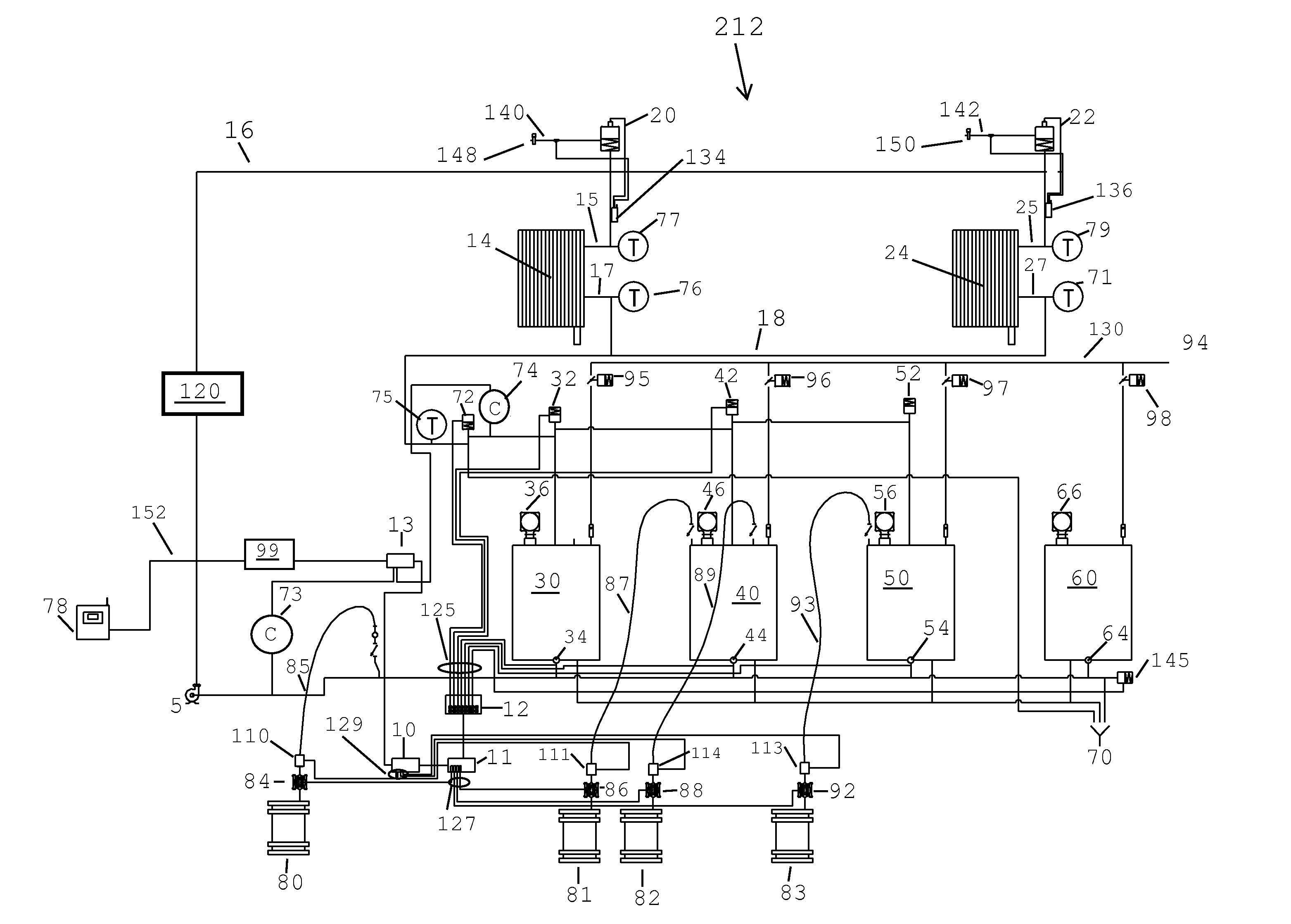
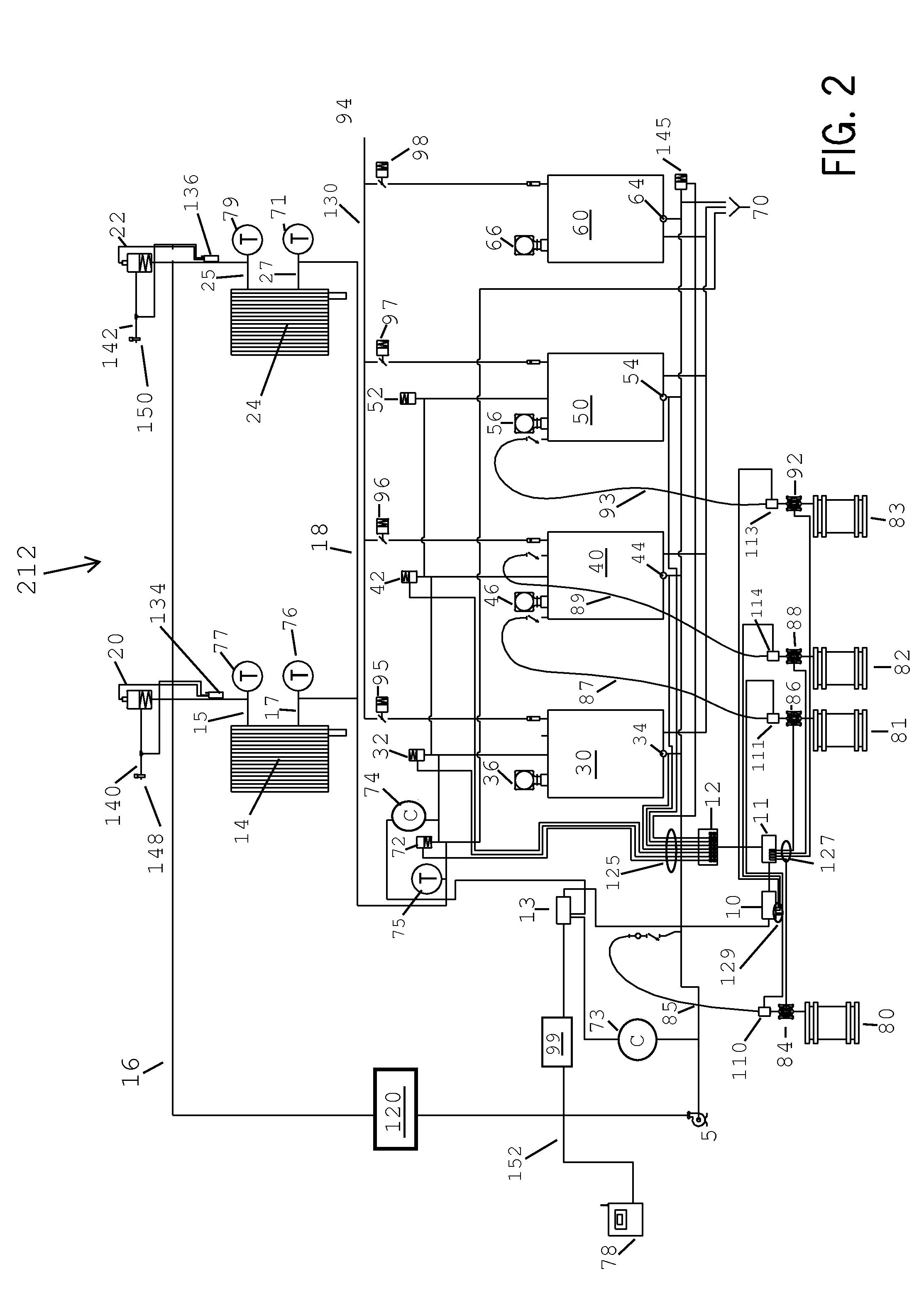
During the clean-in-place process, the controller 78 records temperature signals received from temperature sensor 77 and temperature sensor 79 as a function of time and records air flow signals from air flow sensor 148 and air flow sensor 150 as a function of time. Monitoring both the temperature of a component of cleaning solution at temperature sensor 77 and temperature sensor 79 and the air flow in lines 140 and 142 provides a validation step to ensure that the clean-in-place system 212 is working properly. In order to begin the clean-in-place process, an operator manually enters the desired cleaning location into the controller 78. When apparatus 14 is cleaned and / or disinfected, air flows through line 140, which activates valve 20 and directs the cleaning fluid into apparatus 14. The cleaning solution is heated when it passes through heat exchanger 120. An increase in the temperature signal of temperature sensor 77 verifies that valve 20 opens when directed. When apparatus 24 i...

third embodiment

During the clean-in-place process, the controller 78 records conductivity signals from conductivity sensor 46, conductivity sensor 56, and conductivity sensor 73 as well as flow rate signals from flow meter 110, flow meter 111, flow meter 114, and flow meter 113 as a function of time. When flow meter 111 or 114 outputs signals indicating fluid flow, conductivity sensor 46 should register an increase in pH in alkaline tank 40. When flow meter 113 outputs signals indicating fluid flow, conductivity sensor 50 should register a decrease in pH in acid tank 50. This provides a validation that the pumps are working properly and the conductivity sensors are not fouled or malfunctioning.

After one or more cleaning cycles of the clean-in-place process, the data stored in the controller 78 may be downloaded to a lap top computer or to a wireless PDA and printed and analyzed. The data may be analyzed by the user or by software in the computer or controller. The data provides as a function of tim...


PUM

PropertyMeasurementUnit
Acidityaaaaaaaaaa
Acidityaaaaaaaaaa
Acidityaaaaaaaaaa

Abstract

A controller and recorder is disclosed for controlling, monitoring, and recording concentrations, temperature, air flow, fluid flow, and valve position a cleaning system. The invention allows a user to monitor multiple outputs at one time to quickly and efficiently diagnose malfunctions in the cleaning system. The invention records and archives the outputs during operation of the cleaning system. The data may then be downloaded by a user and analyzed for malfunctions in the system. For example, the data may indicate malfunctioning valves or fouled sensors in the cleaning system.

Description

CROSS-REFERENCE TO RELATED APPLICATIONNot Applicable.STATEMENT REGARDING FEDERALLY SPONSORED RESEARCH OR DEVELOPMENTNot Applicable.BACKGROUND OF THE INVENTION1. Field of the InventionThe present invention relates to a device and methods for controlling, monitoring, and recording chemical concentrations, temperature, flow rate, air flow, and valve stem position in a clean-in-place system or similar automated washer.2. Description of the Related ArtFood processing equipment, such as that found in dairies, tanks, pumps, valves and fluid piping, typically includes, tanks, pumps, valves, and fluid piping. This food processing equipment often needs to be cleaned between each lot of product processed through the equipment. However, the tanks, pumps, valves, and piping can be difficult to clean because the various components may be difficult to access and disassemble for cleaning. Because of these cleaning difficulties, many food processing plants now use clean-in-place systems in which the...

Claims


Application Information

Patent Timeline
IPC IPC(8): B08B7/04
CPCB08B9/027B67D1/07B08B9/0325
Inventor KENOWSKI, ANDYBOHANON, LEO F.
Owner KENOWSKI ANDY
Why Eureka
Try Eureka