
Method and a device for removing mercury from a process gas

a technology of process gas and mercury, which is applied in the direction of separation process, dispersed particle separation, chemistry apparatus and processes, etc., can solve the problems of complex process that requires advanced control and expensive equipmen

Active Publication Date: 2011-08-18
GENERAL ELECTRIC TECH GMBH
View PDF5 Cites 11 Cited by
  • Summary
  • Abstract
  • Description
  • Claims
  • Application Information

AI Technical Summary

Benefits of technology

The present invention provides a method for more effectively removing mercury from a process gas by using a mercury absorbing sorbent and a filtering surface. The method involves measuring the amount of mercury and material collected on the filtering surface, and using the measured data to determine when the filtering surface needs to be cleaned. This method allows for increased mercury removal capacity without increasing the amount of sorbent consumed. The method also takes into account the concentration of mercury in the process gas upstream of the filter, and the pressure drop over the filter to control the cleaning of the filtering surface. The gas cleaning system is more efficient than prior art systems for removing mercury from process gases.

Problems solved by technology

Since mercury is hazardous to the human health and to the environment it is usually necessary to remove mercury from the process gas before it can be discharged into the ambient air.
While the gas cleaning system of U.S. Pat. No. 5,505,766 ensures that a layer of sorbent will always be available on the filter bags for the removal of mercury from the process gas, it is also a complicated process that requires an advanced control and expensive equipment.

Method used


Image

  • Method and a device for removing mercury from a process gas
  • Method and a device for removing mercury from a process gas
  • Method and a device for removing mercury from a process gas

Examples


Embodiment Construction

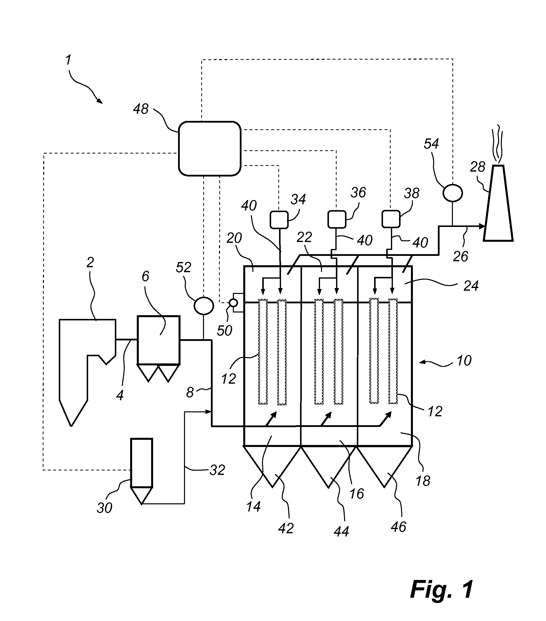
[0036]FIG. 1 is a schematic side view and illustrates a power plant 1, as seen from the side thereof. The power plant 1 comprises a boiler 2. During combustion of a fuel, such as coal or oil, a hot process gas, often referred to as a flue gas, is generated in the boiler 2. The flue gas, which contains polluting substances, including dust particles and mercury, leaves the boiler 2 via a gas duct 4. The gas duct 4 is operative for forwarding the flue gas to a primary dust collector 6, which is optional, in the form of, e.g., an electrostatic precipitator, an example of which is described in U.S. Pat. No. 4,502,872, or a bag house, an example of which is described in U.S. Pat. No. 4,336,035. The primary dust collector 6 is operative for removing the major amount of dust particles from the flue gas.

[0037]A gas duct 8 is operative for forwarding the flue gas from the primary dust collector 6 to a secondary dust collector 10. The secondary dust collector 10 is a fabric filter, by which is...


PUM

PropertyMeasurementUnit
concentrationaaaaaaaaaa
concentrationsaaaaaaaaaa
pressure dropaaaaaaaaaa

Abstract

A method of removing mercury from a process gas by means of a sorbent and a filter (10) involves applying said sorbent to at least one filtering surface (12) of the filter (10). A first parameter, which is indicative of the amount of mercury that needs to be removed in said filter (10), and a second parameter, which is indicative of the amount of material that has been collected on said filtering surface (12), are measured. A measured value of said first parameter is compared to a mercury set point. When said measured value of said first parameter is higher than said mercury set point, the cleaning of said filtering surface (12) is delayed, compared to the point in time suggested by a measured value of said second parameter.

Description

FIELD OF THE INVENTION[0001]The present invention relates to a method of removing, at least partly, mercury from a process gas by means of a mercury absorbing sorbent and a filter having at least one filtering surface.[0002]The present invention further relates to a gas cleaning system, which is operative for removing, at least partly, mercury from a process gas, the gas cleaning system comprising a sorbent supply system which is operative for supplying a mercury absorbing sorbent to said process gas, and a filter having at least one filtering surface and being operative for collecting said sorbent.BACKGROUND OF THE INVENTION[0003]In the combustion of a fuel, such as coal, oil, peat, waste, etc., in a combustion plant, such as a power plant, a hot process gas is generated, such hot process gas containing, among other components, mercury, Hg. Since mercury is hazardous to the human health and to the environment it is usually necessary to remove mercury from the process gas before it ...

Claims


Application Information

Patent Timeline
Patent Type & Authority Applications(United States)
IPC IPC(8): B01D53/30B01D53/02
CPCB01D46/0036B01D46/02B01D46/44B01D53/0454B01D53/10B01D53/30B01D2257/602B01D46/446
Inventor LINDAU, LEIF A.V.
Owner GENERAL ELECTRIC TECH GMBH
Learn More