
Apparatus and method for forming a hole in a hollow organ

a hollow organ and apparatus technology, applied in the field of apparatus and methods for forming holes in hollow organs, can solve the problems of affecting the operation efficiency of the device, and affecting the internal heart structure, so as to prevent the sticking of the cam mechanism

Inactive Publication Date: 2011-08-11
CORREX
View PDF56 Cites 0 Cited by
  • Summary
  • Abstract
  • Description
  • Claims
  • Application Information

AI Technical Summary

Benefits of technology

Accordingly, the invention provides a safety latch that keeps the expansion element in a fully expanded state (i.e. the fourth state) covering the sharp edge of the cutting element to protect the inner surfaces of the hollow organ (i.e. the heart) until the safety latch is released by a deliberate action of the surgeon. In this way, the surgeon can push and rotate the hole forming element while positioning the connector conduit in the apex wall without damaging the inner surfaces of the heart.
In addition, the invention provides a safety latch that the surgeon cannot deliberately or inadvertently release before the sequencing bolt is at the proper position. Furthermore, the invention provides relief to the requirement that the expansion element be moved to be at least partially disposed in the hole forming element, thereby preventing sticking of the cam mechanism during reloading. Also, the invention provides an applicator that cuts a hole in the heart wall without simultaneously implanting a connector conduit in the heart wall.

Problems solved by technology

The major obstacle to widespread adoption of this superior configuration is the nearly complete lack of efficient devices to perform the procedure.
The force may significantly deform the heart to prevent placement of the conduit or even harm internal heart structures.
The endoscopic procedure appears complicated.
Coordination of these steps with a user-friendly interface may be challenging.
This does not provide a tight fit between the cannula and cored heart wall to prevent blood loss from the cored heart wall and from the ventricle and relies entirely upon the sutured attachment ring to achieve hemostasis thus providing a period of time during which there could be great losses of blood.
However, such a tight fit requires substantial axial and torsional forces to be applied to the cannula.
The flexible endoscopic instrument disclosed in Nieman may not provide such forces to be transmitted.
However, substantial axial force is required to cleanly penetrate the myocardium, and such force is not easily applied by a corkscrew.
Further, the pointed tip of the corkscrew can damage other areas of the heart wall (e.g., the septum) while applying axial force and rotation.
However, the balloon is a separate instrument that cannot be combined with the corkscrew.
Use of a trocar makes it difficult to achieve hemostasis during a procedure on a beating heart.

Method used


Image

  • Apparatus and method for forming a hole in a hollow organ
  • Apparatus and method for forming a hole in a hollow organ
  • Apparatus and method for forming a hole in a hollow organ

Examples


Embodiment Construction

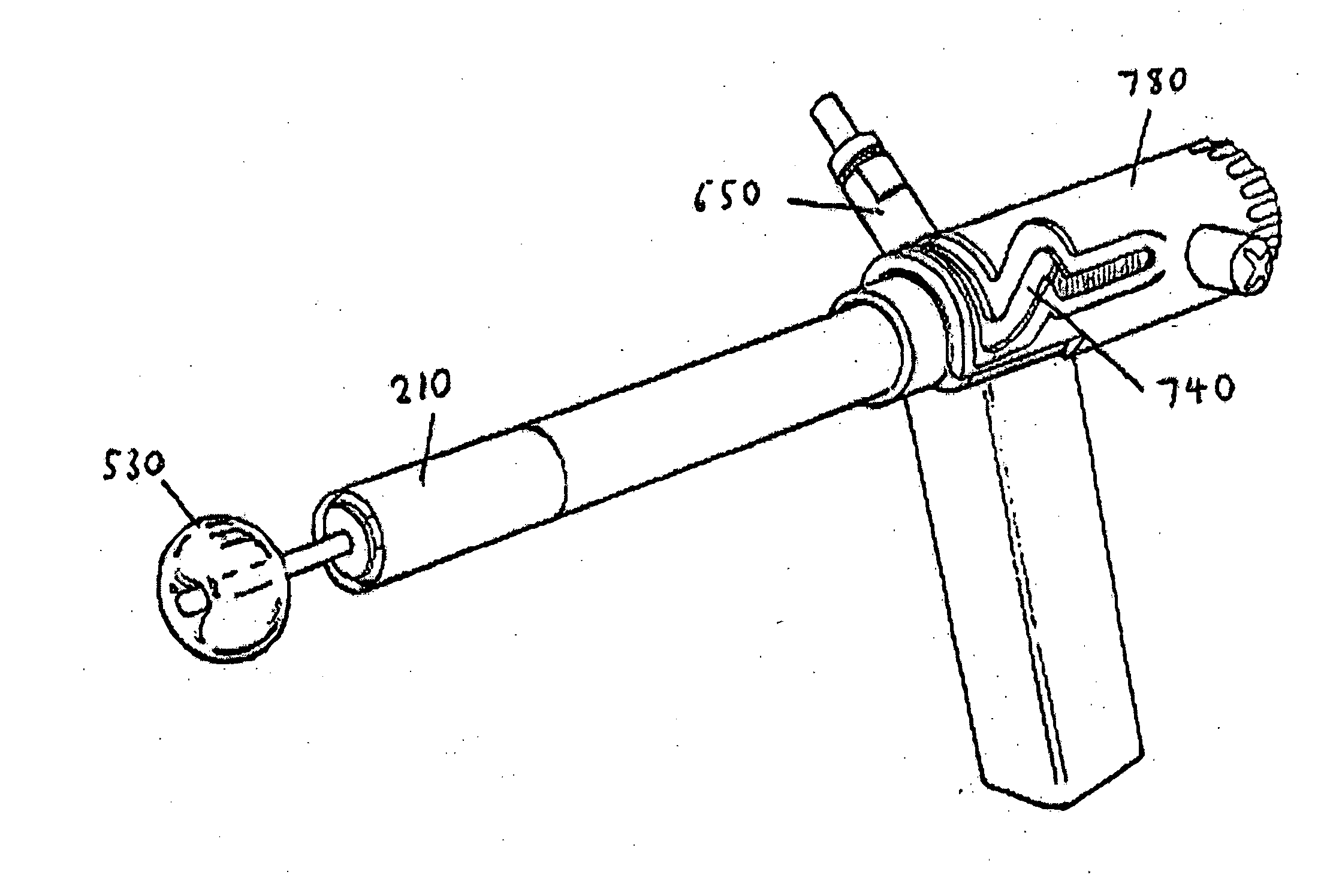
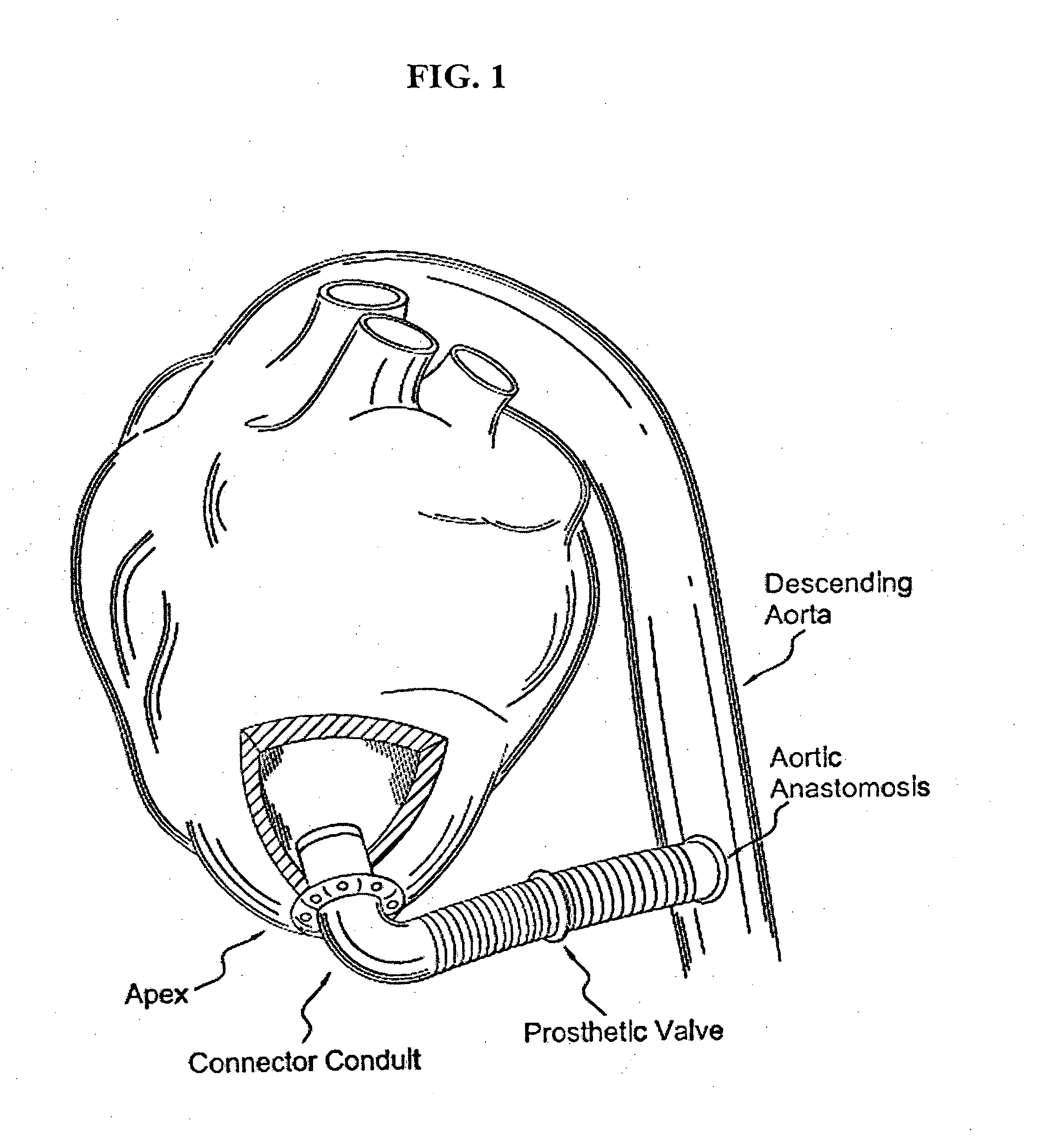
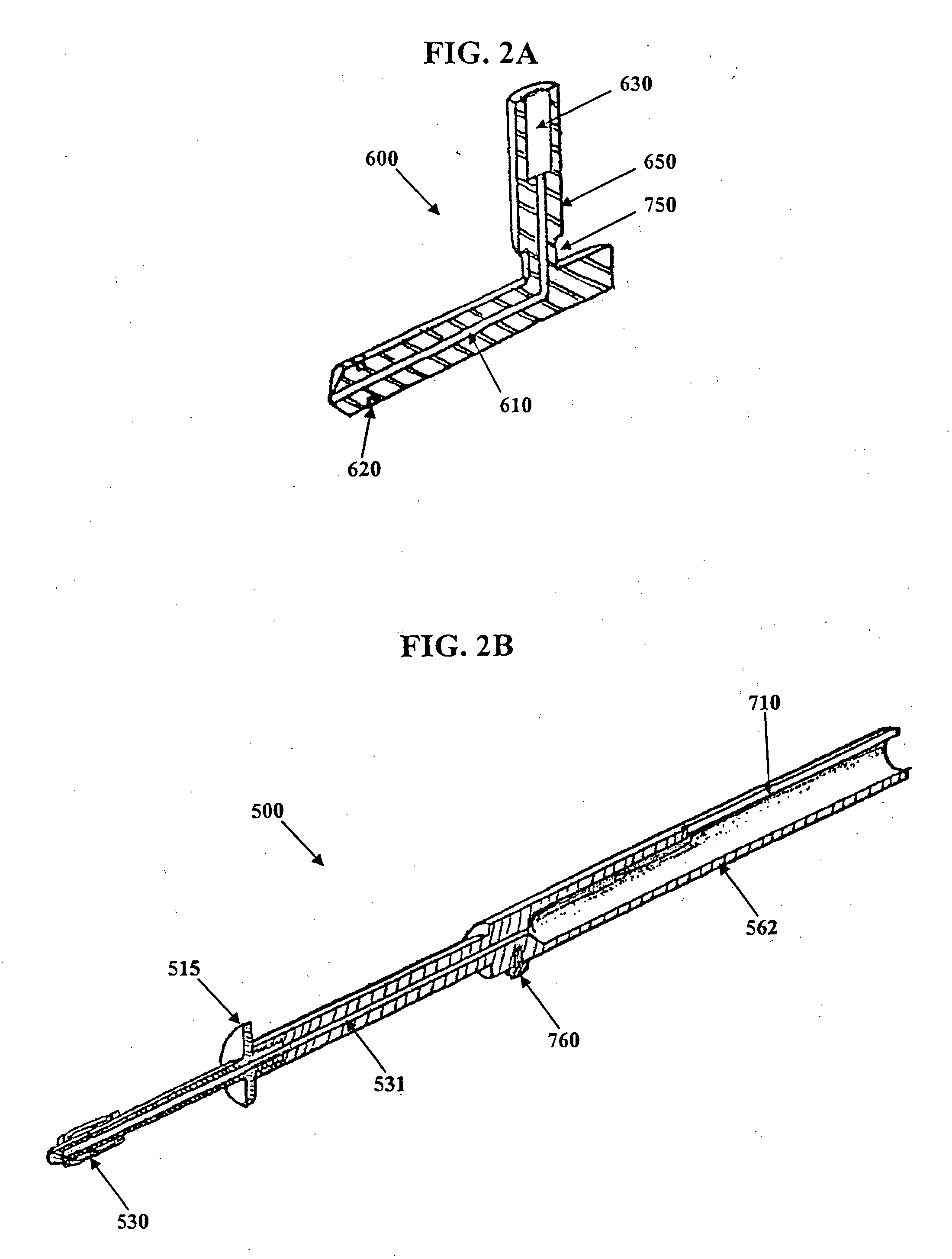
Referring now to the figures, related U.S. Patent Application Publication No. 2005-0251187 to Beane, et al., which is incorporated herein by reference in its entirety, describes use of a sequencing element (such as a cam mechanism) that helps to ensure that critical steps of implanting a connector conduit into the apex of the left ventricle are performed in the proper sequence. (See FIG. 1). Once a tissue plug is created, the sequencing element partially reduces the diameter of the expanding element so that the expanding element can enter the inner diameter of the cutting element while remaining of large enough diameter to prevent the tissue plug from sliding off of the retractor element.

For example, the '187 patent application publication relates to an applicator for forming a hole in a wall of a hollow organ and for inserting a connector conduit into the hole to facilitate connection of the connector conduit to the hollow organ. The applicator includes a hole forming element for f...


PUM


Abstract

The invention relates to an apparatus and method for forming a hole in a wall of a hollow organ. The applicator includes a hole forming element for forming a hole in the wall of the organ, a positioning means for positioning the hole forming element, and a retractor element. In addition, the applicator includes a sequencing means for coordinating the relative movement of the retractor element and the hole forming element in a sequential manner to thereby carry out a procedure for forming a hole in the wall of the hollow organ. The sequencing means may further include a safety latch element operatively coupled to the retracting means and the hole forming element. The safety latch of the invention keeps prevents damage to the internal surface of the organ during the formation of the hole.

Description

FIELD OF THE INVENTIONThe present invention relates to an apparatus and method for forming a hole in a hollow organ, and more particularly, to a surgical device and method for forming a hole in a heart.BACKGROUND OF THE INVENTIONAs the average age of the United States population increases, so do the instances of aortic stenosis. An alternative approach to the conventional surgical replacement of the stenotic aortic valve involves the use of an apicoaortic conduit. In this approach, the native aortic valve is not removed, and a prosthetic valve is implanted in a parallel flow arrangement. A connection conduit (or tube) connects the apex of the heart to the descending aorta. Somewhere along this conduit, the prosthetic valve is interposed. Thus, blood leaves the heart through the apex and travels through the conduit (with valve) to the descending aorta.Until recently, surgical procedures to implant an apicoaortic conduit have included a single, long incision, such as in the 6th interc...

Claims


Application Information

Patent Timeline
Patent Type & Authority Applications(United States)
IPC IPC(8): A61B17/32
CPCA61B17/0218A61B17/11A61B17/320016A61B17/32053A61B2017/00243A61F2/064A61B2017/00252A61B2017/00557A61B2017/0237A61B2017/1107A61B2018/00392A61B2017/00247
Inventor BEANE, RICHARD M.BROWN, JOHN W.CRUNKLETON, JAMES ALANGAMMIE, JAMES S.SMITH, JR., JOSEPH L.
Owner CORREX
Learn More