
Segmented wind turbine airfoil/blade

Inactive Publication Date: 2011-08-11
DUGGAL ENERGY SOLUTIONS
View PDF13 Cites 16 Cited by
  • Summary
  • Abstract
  • Description
  • Claims
  • Application Information

AI Technical Summary

Benefits of technology

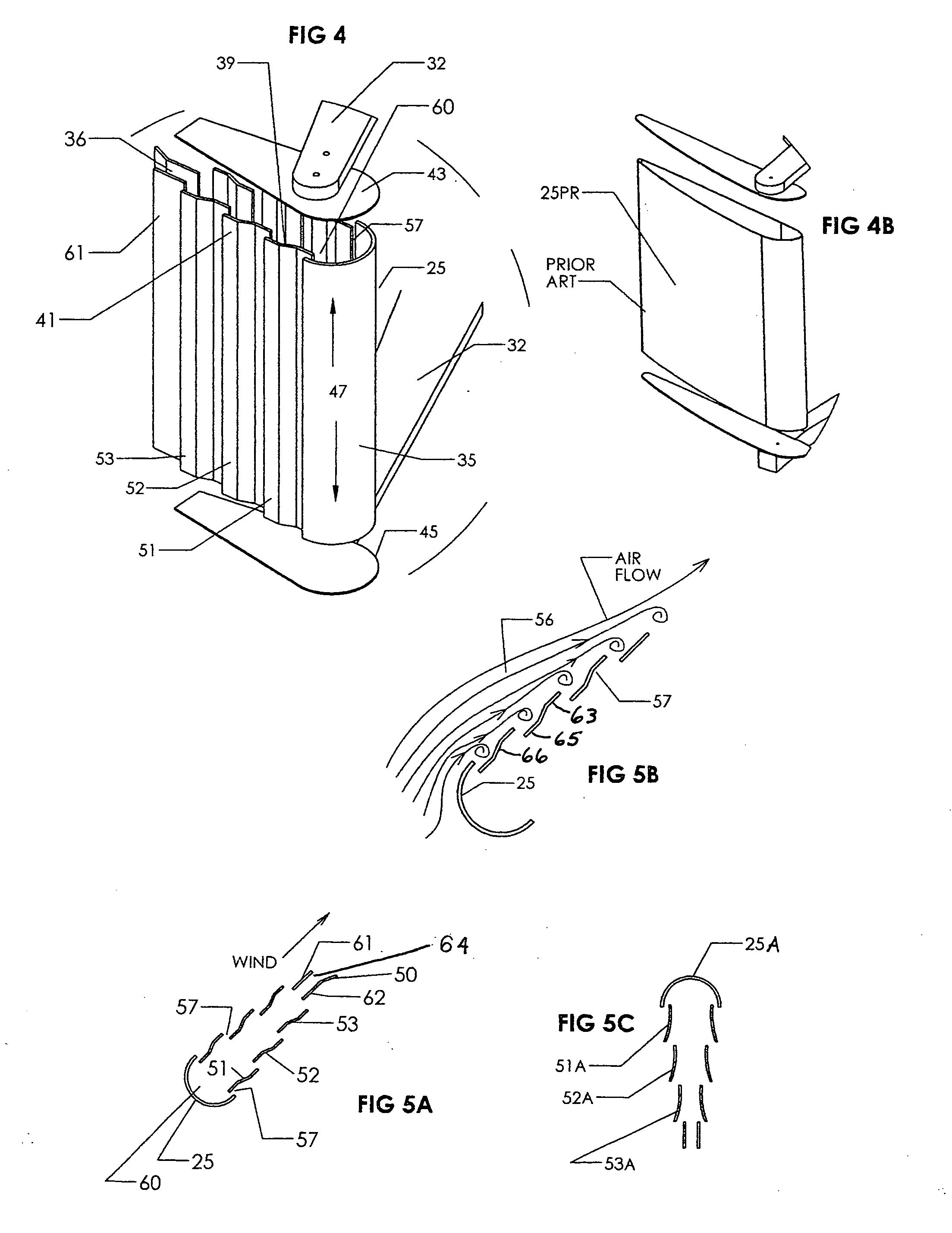
[0003]This invention relates to wind turbines and more particularly to vertical axis wind turbines having wind foils of the airfoil type. It is an object of the present invention to provide a vertical axis wind turbine wind foil which airfoil is hollow and includes plurality of plate segments mounted in spaced contiguous relation to form openings there between. The foregoing feature provides airflow entry ports into the hollow airfoil and enable the wind to thrust against the segments and to enter into said airfoil and thrust against the interior thereof to push the airfoil forward. Also, the wind / airflow thrusts against the segments which more efficiently enables capture of wind energy than prior art blades regardless of the position of the foil in the rotating cycle or arc around the vertical axis. The invention provides an efficient high torque as well as a high starting torque.

Problems solved by technology

However, in many prior art vertical axis turbines, the starting torque is low.

Method used


Image

  • Segmented wind turbine airfoil/blade
  • Segmented wind turbine airfoil/blade
  • Segmented wind turbine airfoil/blade

Examples


Embodiment Construction

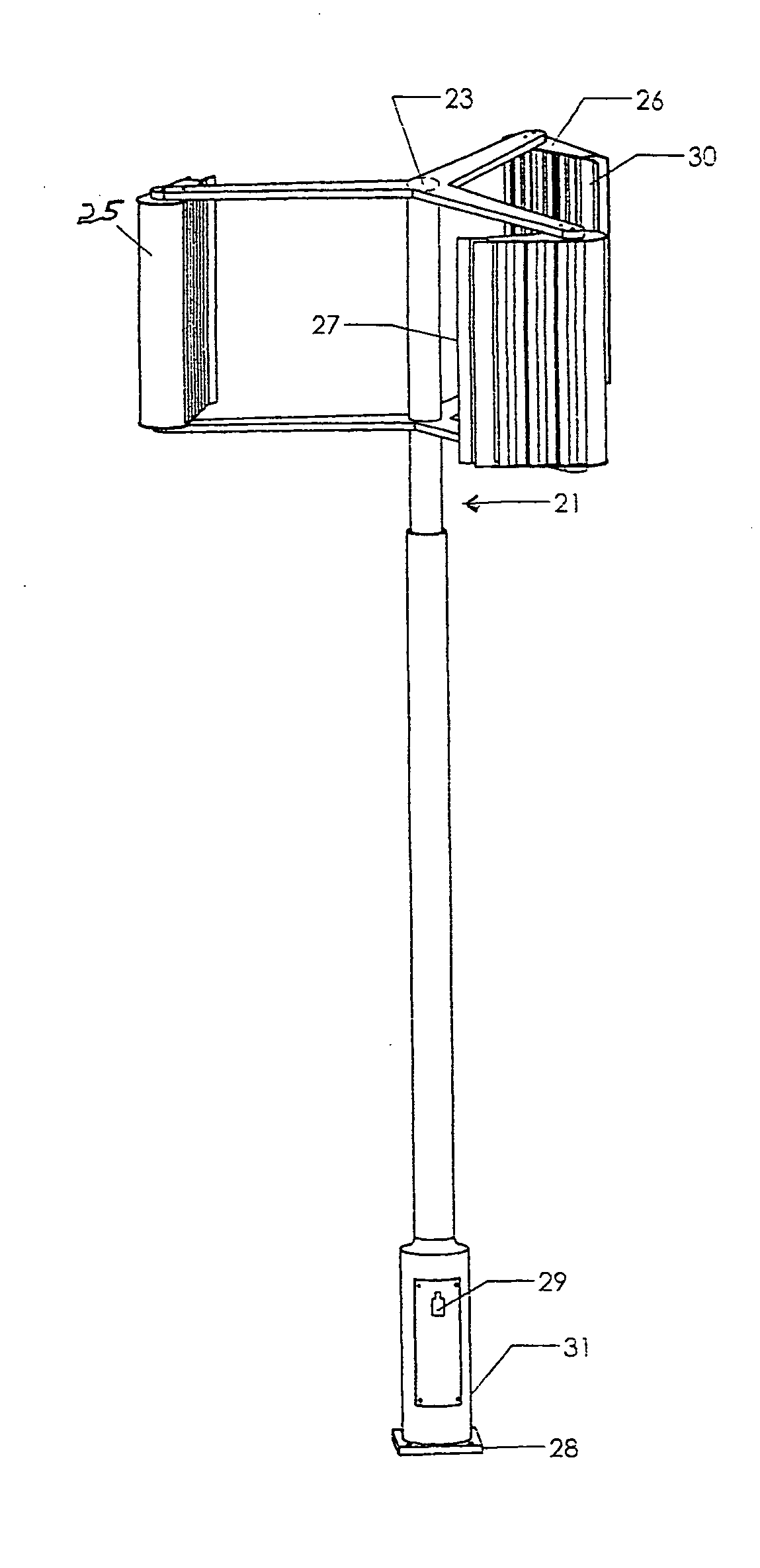
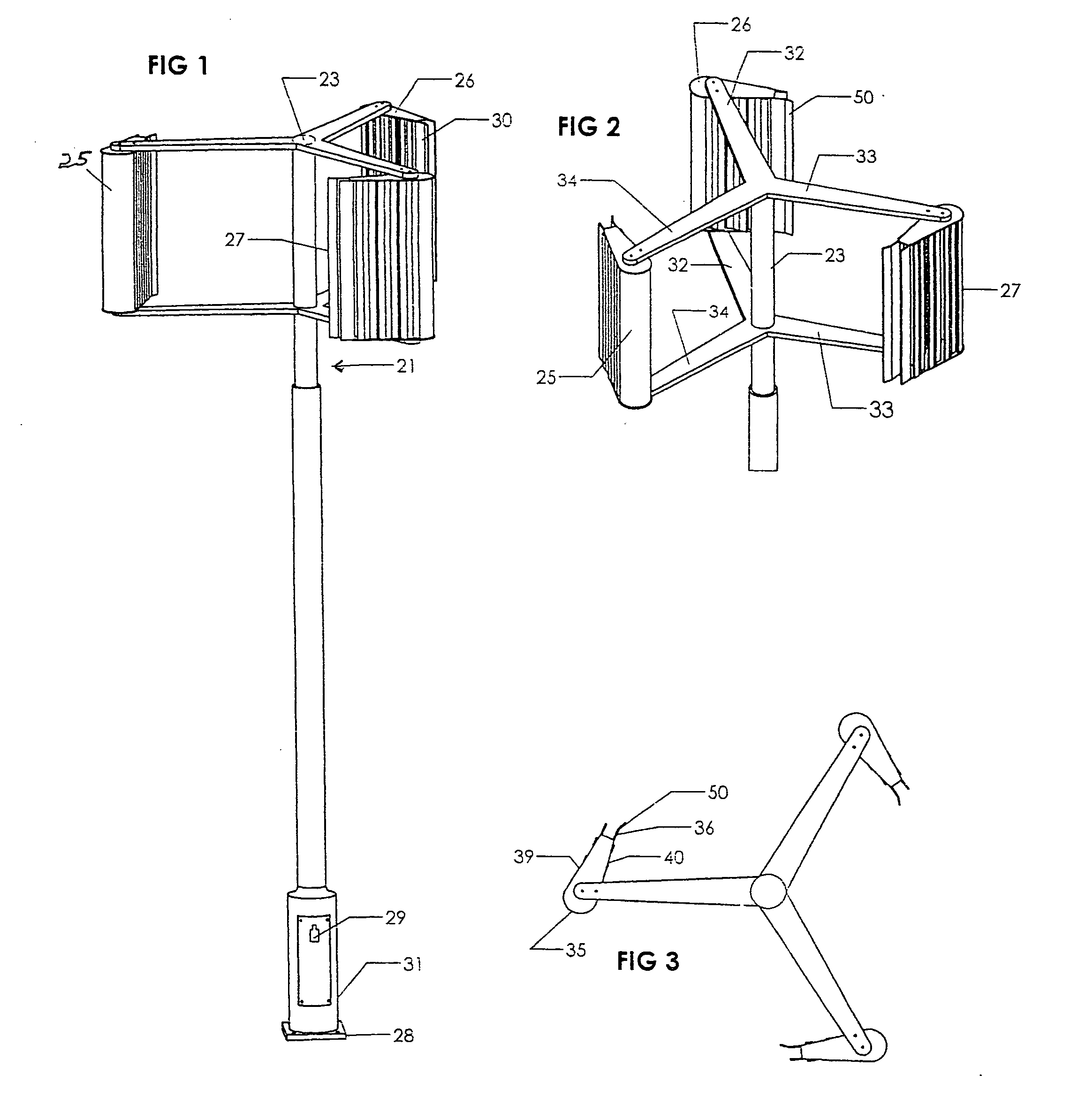
[0015]FIG. 1 shows a vertical axis wind turbine assembly 21 having a rotatable shaft 23 that provides a central axis of rotation for the segmented airfoils / wind foils 25, 26 and 27 and is an example of a preferred structure. In the preferred embodiment described herein the airfoils are symmetrical in shape, although other standard shapes may be used. The wind turbine 21 is supported on a suitable base 28. In the embodiment shown an electrical generator 29 is mounted on a housing 31 that also encloses the shaft 23. As is well known, the generator 29 includes a suitable rotor rotated by shaft 23 which cooperates with a stator to generate electrical energy.

[0016]While three airfoils are shown in the wind turbine system disclosed herein, it will be appreciated that more airfoils may be used in the system. Vertical axis wind turbine systems having three or more airfoils are commonly used and the airfoils of this invention are applicable for use in a majority of such systems.

[0017]Refer n...


PUM


Abstract

A wind foil blade / airfoil for a wind turbine wherein the airfoil includes a series of vertical segments having unique offset shapes to provide openings between segments enabling the segments to function as wind sails when moving downwind to thrust the blade forward and to act as an airfoil when the blade is moving into and upwind, wherein the wind foil blade has a high forward thrust.

Description

[0001]This application claims the priority filing date of provisional patent application USPTO application No. 61 / 337,665 having a filing date of Feb. 11, 2010, titled “Segmented Wind Turbine Airfoil / blade, the applicant being Troy W. Livingston, the same inventor hereof.BACKGROUND OF INVENTION[0002]Wind power turbines are largely divided into vertical axis wind power turbines and horizontal axis wind power turbines. The present invention is directed to a vertical axis wind power turbine and more particularly to the turbine foils / blades used in such vertical axis turbines. As is known, vertical axis wind turbines are often omni-directional, and are not influenced by the wind direction and have certain advantages over the horizontal axis turbines. However, in many prior art vertical axis turbines, the starting torque is low. Further the design of prior art wind / airfoils for vertical axis turbines need improvements in efficiency. This is the case because the vertical rotation of the a...

Claims


Application Information

Patent Timeline
IPC IPC(8): B63H1/06
CPCB63H9/00F03D3/061Y02E10/74F05B2240/302F03D3/065F03D3/062
Inventor LIVINGSTON, TROY W.
Owner DUGGAL ENERGY SOLUTIONS
Learn More