A wave-power unit, and a use of a such

a wave-power unit and wave-power technology, applied in the direction of sliding contact bearings, electric generator control, machines/engines, etc., can solve the problems of insufficient precision, risk of operation disturbance and breakdown, and the size of the gap can be substantially different from the predetermined, so as to achieve smooth performance, simple and reliable construction, and high degree of symmetry

Inactive Publication Date: 2011-08-11
SEABASED AB
View PDF21 Cites 15 Cited by
  • Summary
  • Abstract
  • Description
  • Claims
  • Application Information

AI Technical Summary

Benefits of technology

[0016]This is a mechanically advantageous arrangement that provides a well controlled cooperation between the rolling elements and the relatively moving parts.
[0045]Also with this embodiment a high spread of the mechanical forces is obtained.

Problems solved by technology

Since a generator of the type in question may be fairly large, insufficient precision in the guiding entails that the size of the gap risks deviating substantially from the predetermined one.
This entails asymmetry of the occurring magnetic forces, which results in harmful asymmetric forces on the translator with the risk of operational disturbances as well as breakdown.
Also the electromagnetic transformation of energy is effected negatively by erroneous gap size.

Method used


Image

  • A wave-power unit, and a use of a such
  • A wave-power unit, and a use of a such
  • A wave-power unit, and a use of a such

Examples


Embodiment Construction

OF THE INVENTION

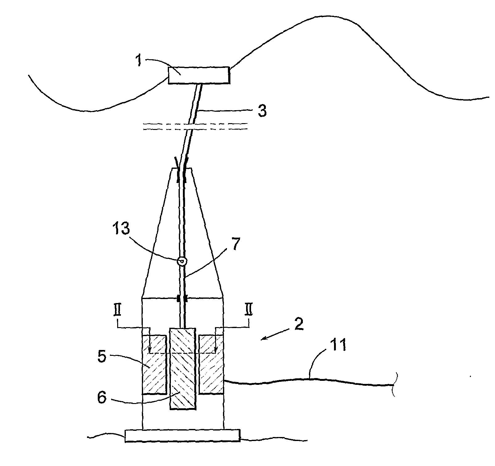
[0058]FIG. 1 is a schematically side view of a wave-power unit according to the invention in operation in the sea. A floating body 1 floats on the sea surface and is connected by a connection means 3, 7, to a linear generator 2 anchored at the sea bed. The connection means consists of an upper part 3, which is a wire, rope, chain or the like and a lower part 7 which is a rigid rod. The wire 3 is connected to the rod 7 by a joint 13. In the figure the generator is attached at the sea bed. It is, however, to be understood that the generator can be located above the sea bed and be anchored in some other way.

[0059]The linear generator 2 has a stator 5 with windings and a translator 6 with magnets. The translator 6 is able to reciprocate up and down within the stator 5 thereby generating current in the stator windings, which current by an electric cable 11 is transferred to an electric network.

[0060]When the floating body 1 due to the wave movements of the sea surface is ...


PUM


Abstract

The invention relates to a wave-power unit for the production of electric power. It comprises a floating body arranged for floating on the sea and an electric linear generator with a stator (5) and a reciprocating translator (6). The stator (5) is arranged to be anchored in the bed of a sea and the translator (6) is connected to the floating body by connection means, The translator (6) is journalled in a plurality of roiling elements (15) such that a circumferential gap (14) is formed between the stator and the translator. According to the invention each rolling element (15) has an elasticity that is low enough to meet the condition that a change in the width (d) of the gap results in a change in the total force from the roiling elements (15) that is larger than the total magnet forces on the translator resulting from the change in width (d). The invention also relates to a use of the invented wave-power unit.

Description

FIELD OF INVENTION[0001]The present invention in a first aspect relates to a wave-power unit for the production of electric power and comprising a floating body arranged for floating on the sea and an electric linear generator having a stator and translator reciprocating along a center axis, the stator being arranged to be anchored in the bed of a sea and the translator being connected to the floating body by connection means, which translator is journalled in a plurality of rolling elements such that a circumferential gap is formed between the stator and the translator.[0002]In a second aspect the invention relates to a use of such a wave-power unit.[0003]in the present application the terms “axial”, “radial” and “circumferential” refer to the axes defined by the reciprocating movement of the centre of the translator if not explicitly stated otherwise. The terms “upper” and “lower” refer to the vertical direction and relates to the orientation of the components in question when the...

Claims


Application Information

Patent Timeline
IPC IPC(8): F03B13/18H02K35/00
CPCF03B13/1885H02K7/1876Y02E10/38F05B2250/41F05B2220/707F05B2240/50F03B13/1865Y02E10/30F03B13/18F03B13/26H02K35/00
Inventor LEIJON, MATSGUSTAFSSON, STEFAN
Owner SEABASED AB
Why Eureka
Try Eureka