
Air intake structure for a turbine engine nacelle

Inactive Publication Date: 2011-08-11
AIRCELLE
View PDF7 Cites 9 Cited by
  • Summary
  • Abstract
  • Description
  • Claims
  • Application Information

AI Technical Summary

Benefits of technology

[0017]The air intake structure of the invention includes an air intake lip whereof the inner wall has an extension beyond the partition, in the downstream direction of the air intake structure of the invention. As a result, the interface zone supported by said extension is also moved further downstream than that of the prior art. Thus, the interface zone then undergoes very little or no thermal stress and therefore deformation of the air intake lip, which makes it possible to avoid the presence of play in said zone.
[0026]a reinforcing partition is fastened on the extension at the interface zone with the inner panel, which makes it possible to reinforce the structural resistance of the mobile structure while limiting the associated mass gain.

Problems solved by technology

Significant play resulting in the interface zone greatly compromises the performance of the turbojet engine.
As a result, the latter parts undergo significant thermal stresses, which result in structural degradation.

Method used


Image

  • Air intake structure for a turbine engine nacelle
  • Air intake structure for a turbine engine nacelle
  • Air intake structure for a turbine engine nacelle

Examples


Embodiment Construction

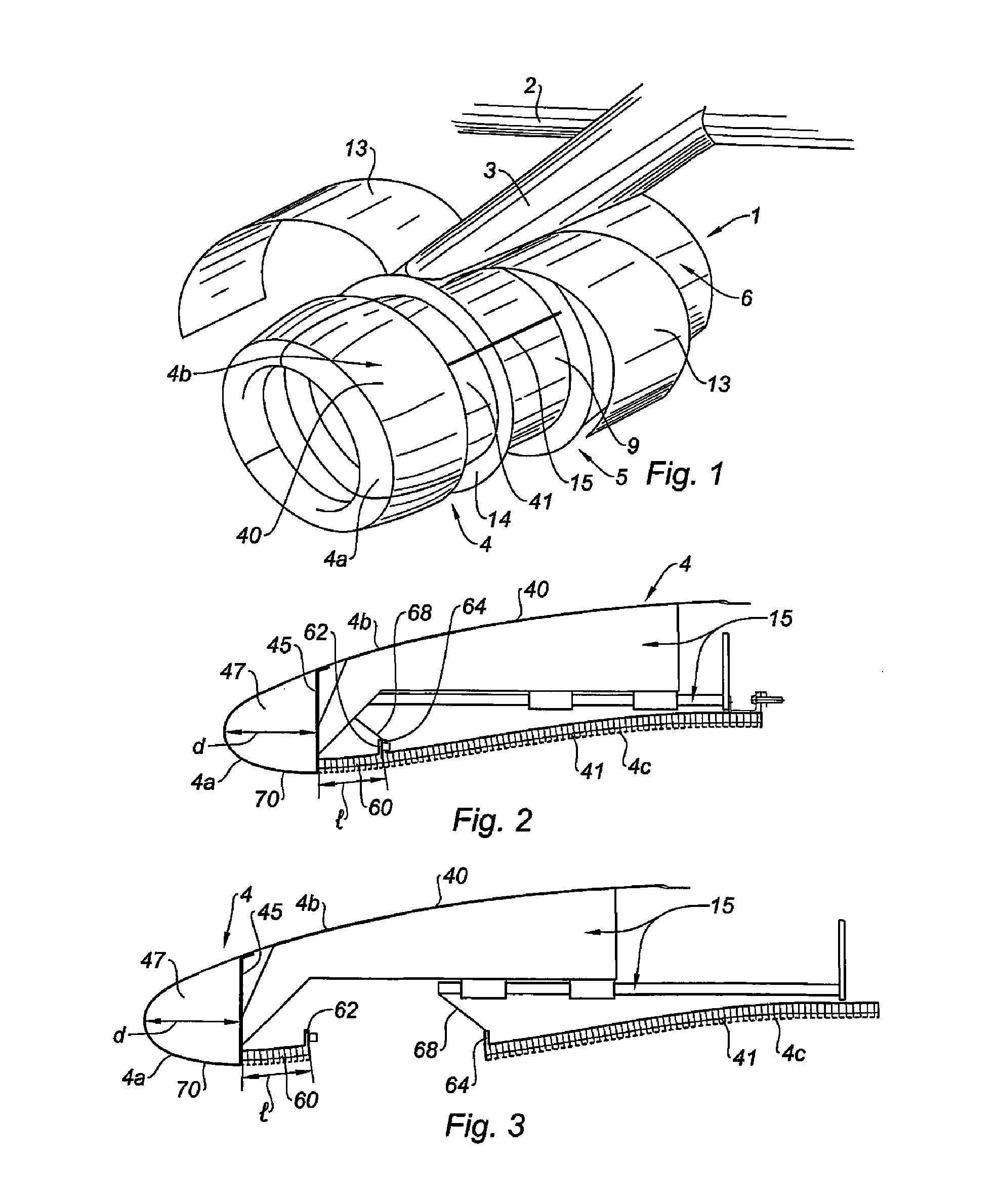
[0035]According to the embodiment illustrated in FIG. 1, a nacelle 1 including an air intake structure according to the invention constitutes a tubular housing for a turbojet engine (not shown) for which it serves to channel the flows of air it generates by defining the inner and outer aerodynamic lines necessary to obtain optimal performance. It also houses different components necessary for the operation of the turbojet engine as well as related systems such as a thrust reverser.

[0036]The nacelle 1 is intended to be attached to a fixed structure of an airplane, such as a wing 2, via a pylon 3.

[0037]More precisely, the nacelle 1 has a structure comprising an air intake structure 4 of the invention upstream, a middle structure 5 surrounding a fan (not shown) of the turbojet engine, and a downstream section 6 surrounding the turbojet engine and generally housing a thrust reverser system (not shown).

[0038]The middle structure 5 includes a casing 9 fastened to an end of the air intake ...


PUM


Abstract

The invention relates to an air intake structure (4) for a turbine engine nacelle for directing an air flow towards the fan of the turbine engine, said structure comprising at least one outer panel (40), at least one inner panel (41) and an air intake lip (4a) having an inner wall (70) to be in contact with the air flow flowing into the turbine engine and a partition (45) separating the air intake lip (4a) from the rest of the nacelle, the air intake lip (4a) having an extension (60) that can be fastened onto the inner panel (41) and that extends substantially as a continuation of the inner wall (70) towards the downstream side of the air intake structure over a length (I) at least equal to about the maximum distance (d) between the partition (45) and the air intake lip (4a). The invention also relates to a nacelle for a turbine engine comprising such an air intake structure (4).

Description

TECHNICAL FIELD[0001]The invention relates to a nacelle for a turbojet engine.BACKGROUND[0002]In general, an aircraft nacelle has a structure comprising an air intake structure, a middle structure and a downstream section. The term “downstream” here refers to the direction corresponding to the direction of the cold air flow penetrating the turbojet engine. The term “upstream” designates the opposite direction.[0003]The air intake structure is situated upstream of the turbojet engine serving to propel the aircraft. Downstream of the air intake structure, the middle structure is intended to surround a fan of the turbojet engine. Still further downstream is the downstream section generally housing thrust reverser means intended to surround the combustion chamber of the turbojet engine. The nacelle ends with a jet nozzle whereof the outlet is situated downstream of the turbojet engine.[0004]The air intake structure comprises at least one outer panel, at least one inner panel and an air ...

Claims


Application Information

Patent Timeline
IPC IPC(8): F02K3/02
CPCB64D29/06B64D33/02B64D2033/0206Y02T50/675F02C7/04F02K1/822Y02T50/672B64D2033/0286Y02T50/60
Inventor VAUCHEL, GUY BERNARDBRAVIN, FABIEN
Owner AIRCELLE
Learn More