
Magnetic Resonance Imaging Apparatus and Method using Squid Detection and Field-Cycling

a magnetic resonance imaging and field-cycling technology, applied in the field of magnetic resonance imaging apparatus and methods, can solve the problems of claustrophobic and unnerving experience, field and operating frequency, and consequent loss of image quality, and achieve the effect of enhancing t1 contras

Active Publication Date: 2011-08-04
GOOD JEREMY A
View PDF2 Cites 13 Cited by
  • Summary
  • Abstract
  • Description
  • Claims
  • Application Information

AI Technical Summary

Benefits of technology

[0024]The preferred embodiment of the present invention uses use the resonant frequency SQUID-based MRI method and changes the procedure and pulse sequences so as to have enhanced T1 contrast.

Problems solved by technology

This can be a claustrophobic and unnerving experience.
It is made worse due to the noisy operation of the gradient coils as images are acquired over a period of typically 15 minutes.
The reduction in field and operating frequency gives lower strength and noisier NMR signals for the detection system to acquire, with a consequent loss of image quality.
The limit in using lower fields is set by the ability of the electronic amplifiers and the resonant detection circuits to detect the signals with an adequate signal to noise ratio.
Another approach to detecting the NMR signals for MRI at low fields, developed in recent years but not yet used in practical systems, is to use a Superconducting Quantum Interference Device known as a SQUID.
Building large magnets to accommodate a whole person with a field homogeneity of a few ppm over say a 400 mm sphere is an expensive and difficult task.
The disadvantages of this approach is first the pre-polarising pulse is difficult to apply and secondly the technique is vulnerable to weak DC magnetic field disturbances which distort the image, as well as a susceptibility to RF and AF interference due to the direct DC coupling of the input coil to the SQUID.

Method used


Image

  • Magnetic Resonance Imaging Apparatus and Method using Squid Detection and Field-Cycling
  • Magnetic Resonance Imaging Apparatus and Method using Squid Detection and Field-Cycling
  • Magnetic Resonance Imaging Apparatus and Method using Squid Detection and Field-Cycling

Examples


Embodiment Construction

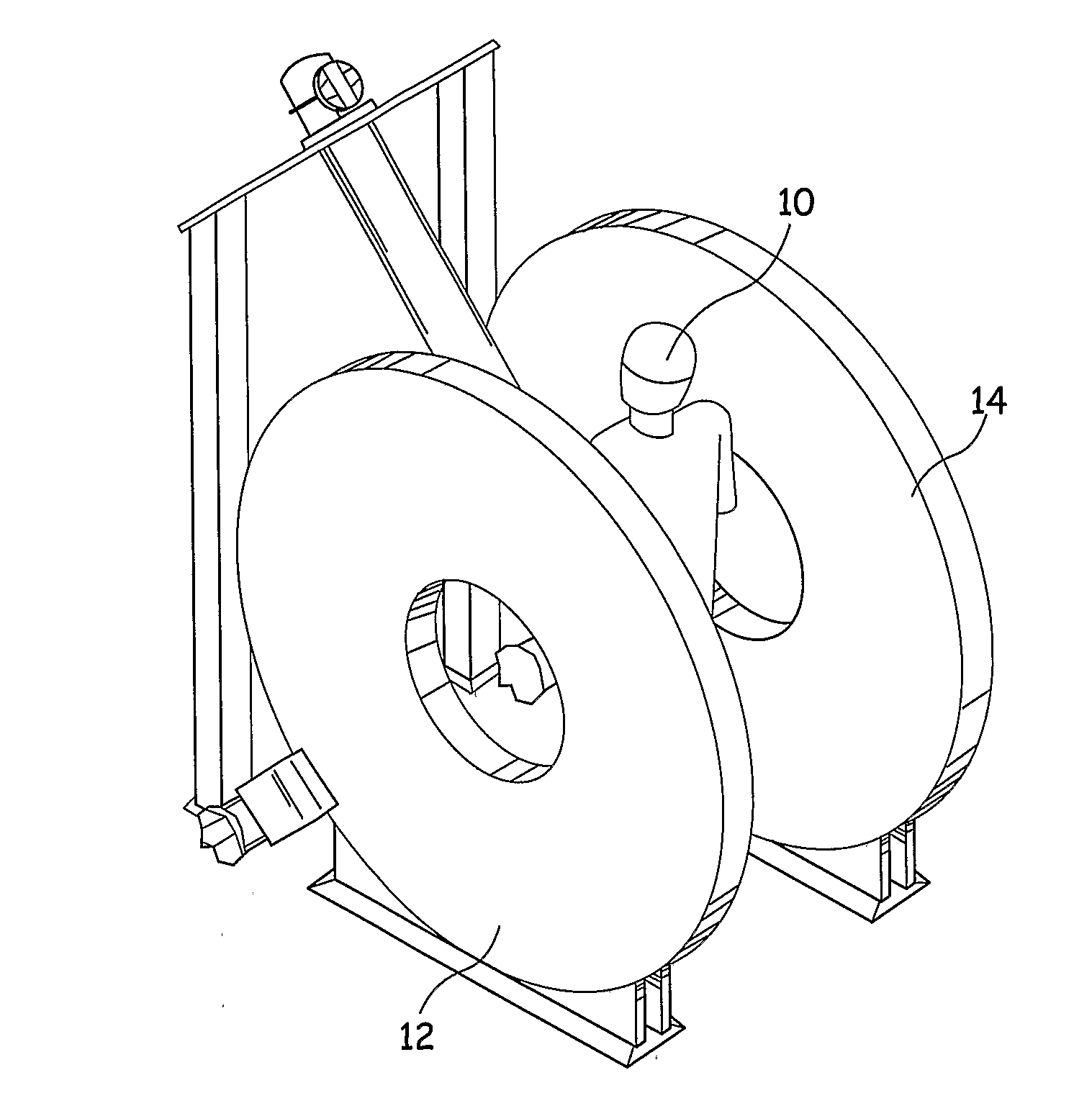
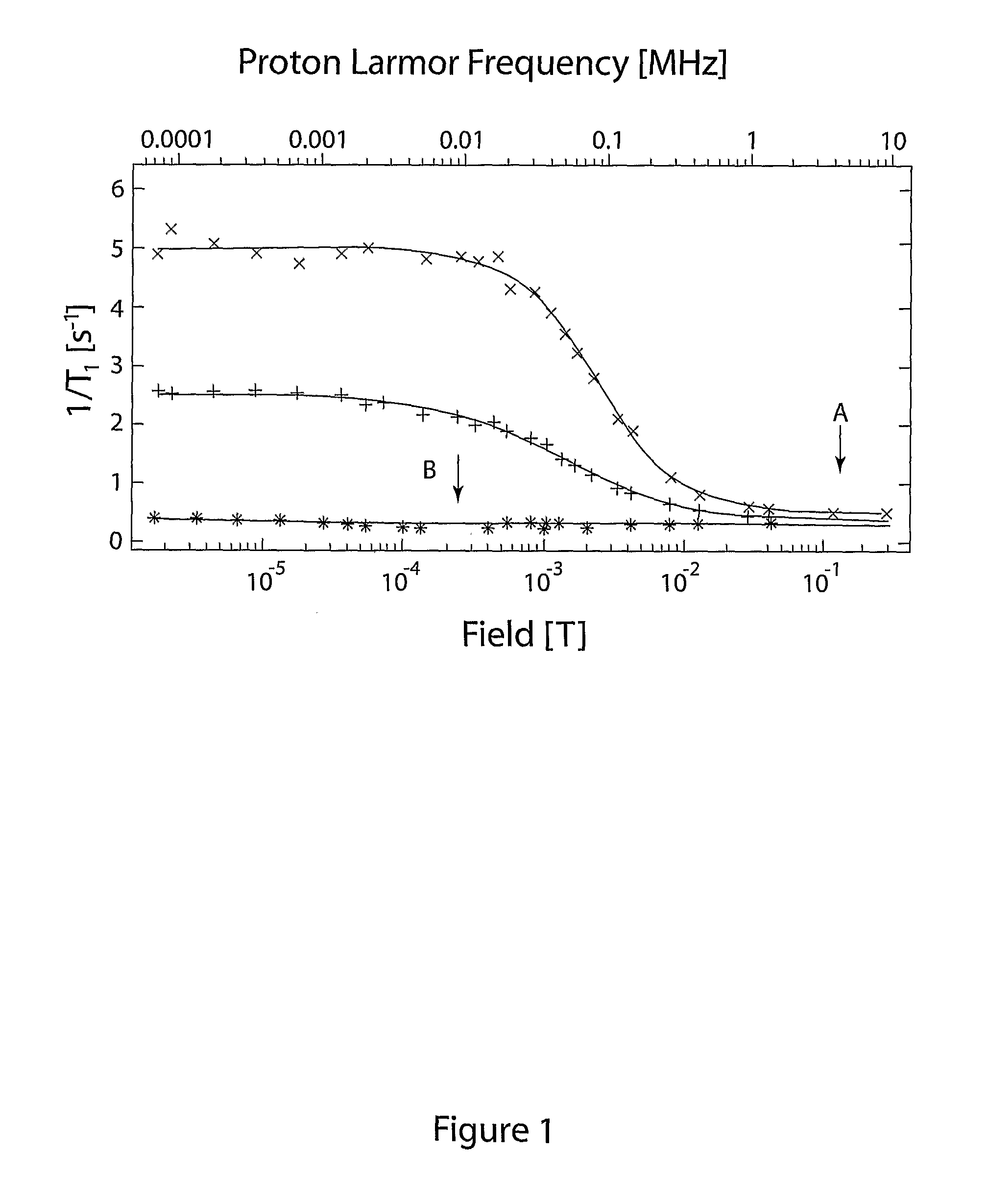
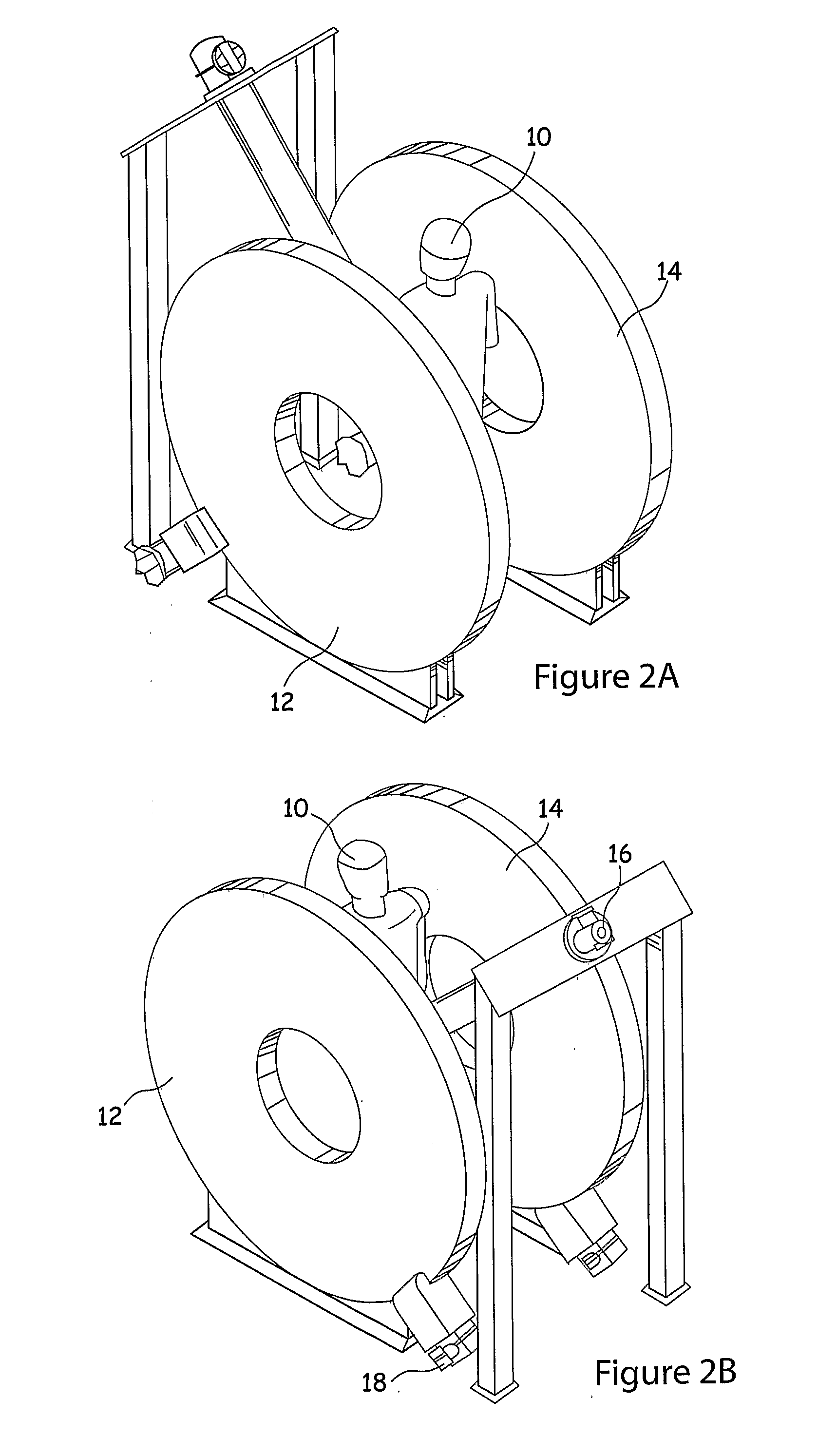
[0032]As an example of the preferred procedure, the DC background field is set to, say, 150 gauss and the 90° RF pulse is applied. The background field is then rapidly reduced to about 10 gauss or less and a period of 0.1-3 seconds is allowed to lapse before the 150 gauss field is re-applied and a 180° pulse is applied to generate a spin echo. In this procedure, during the low field period, the differences in T1 between different tissues, or parts of the sample, means that magnetisation will be lost or reduced in some parts of the sample so that the image is altered. Taking two images, one without the field being cycled and one with field cycling and comparing one image to the other will give an image highlighting the variations of T1. It is considered such images provide very good indications of abnormal human or animal tissues, particularly cancer bearing tissues.

[0033]One great advantage of SQUID based MRI is that the magnetic fields are modest, which means that the stored energy...


PUM


Abstract

There is described an MRI system in which the detection of the NMR signal is performed by a resonant input at a median field range above 100 gauss and where the main field is cycled to a low field of below 50% of the resonant frequency after the excitation of the NMR signal for a period sufficient to develop differences in magnetisation (T1). The advantage of this system is that images can be generated at much lower field intensities than prior art systems and is able to detect abnormalities in tissue such as cancerous tissues in a patient.

Description

FIELD OF THE INVENTION[0001]The present invention relates to magnetic resonance imaging apparatus and methods.BACKGROUND OF THE INVENTION[0002]Magnetic Resonance Imaging for medical and diagnostic applications is normally carried out at magnetic fields of at least 1 Tesla (10,000 gauss), which corresponds to an RF frequency of 42 MHz for the nuclear magnetic resonance (NMR) signal of protons in water which is the major constituent of the body. The high field results in both better polarisation of the hydrogen nuclei and a strong signal at the higher detection frequency. This results in good contrast and spatial resolution. Whole body imaging at this field requires a large solenoid magnet, usually superconducting with high homogeneity typically a few parts per million over a 40 cm sphere. The patient / subject is placed on a bed which slides into the bore of the magnet. This can be a claustrophobic and unnerving experience. It is made worse due to the noisy operation of the gradient co...

Claims


Application Information

Patent Timeline
IPC IPC(8): A61B5/055
CPCG01R33/0354G01R33/326G01R33/445G01R33/3806G01R33/3815G01R33/3804G01R33/48
Inventor GOOD, JEREMY A.
Owner GOOD JEREMY A
Learn More