
Ventilation control apparatus

a technology of ventilation control and control apparatus, which is applied in the direction of ventilation systems, lighting and heating apparatus, heating types, etc., can solve the problems of reducing efficiency and more outside air being taken in wastefully

Inactive Publication Date: 2011-08-04
PANASONIC INTELLECTUAL PROPERTY MANAGEMENT CO LTD
View PDF13 Cites 20 Cited by
  • Summary
  • Abstract
  • Description
  • Claims
  • Application Information

AI Technical Summary

Benefits of technology

[0007]The present invention is made considering such circumstances and has an object to optimize the intake amount of the outside air.

Problems solved by technology

As a result, the smaller the number of people in the space to be air-conditioned is, the more the outside air is taken in wastefully, which reduces efficiency.

Method used


Image

  • Ventilation control apparatus
  • Ventilation control apparatus
  • Ventilation control apparatus

Examples


Embodiment Construction

[0028]At least the following details will become apparent from descriptions of this specification and of the accompanying drawings.

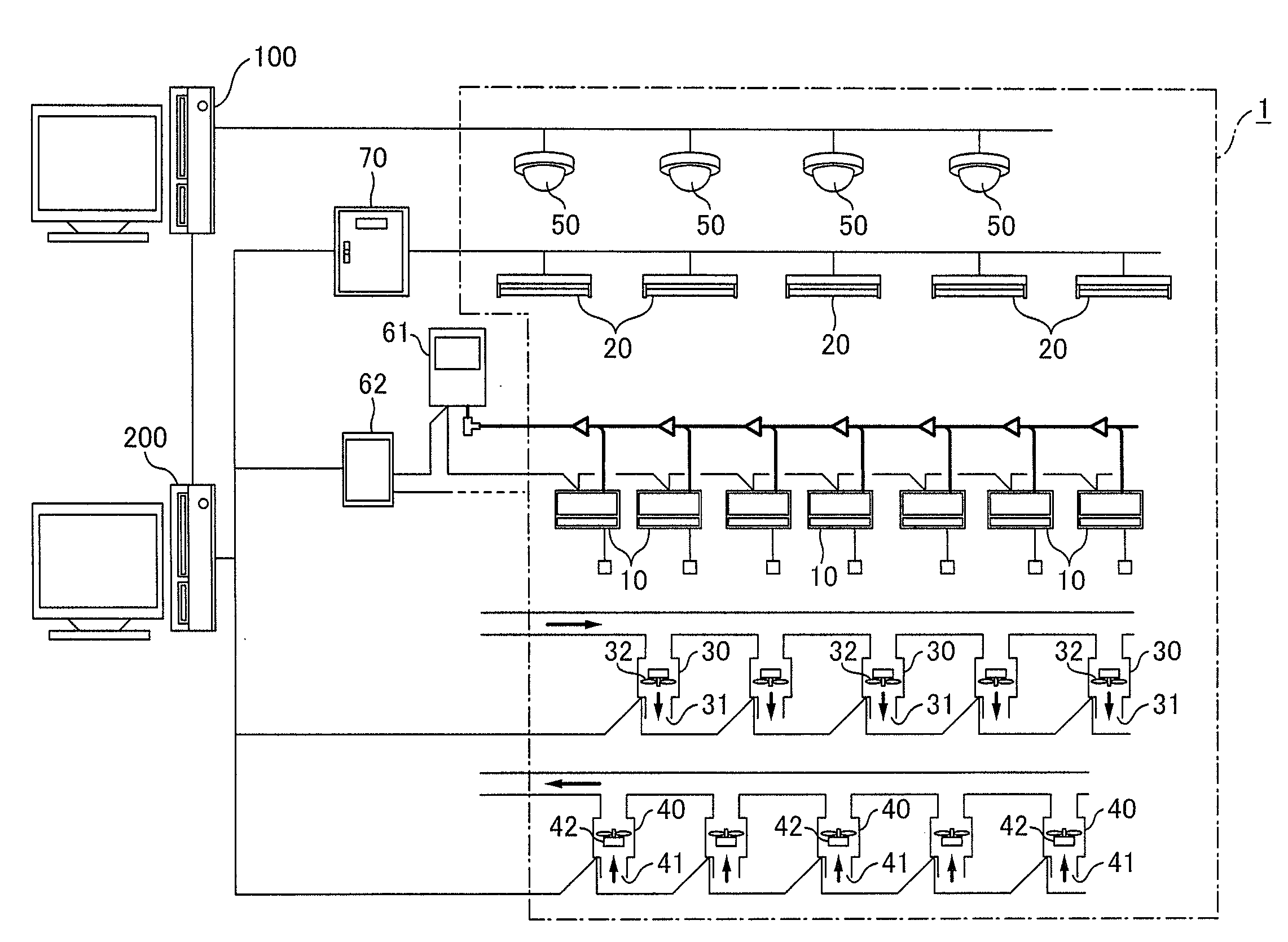
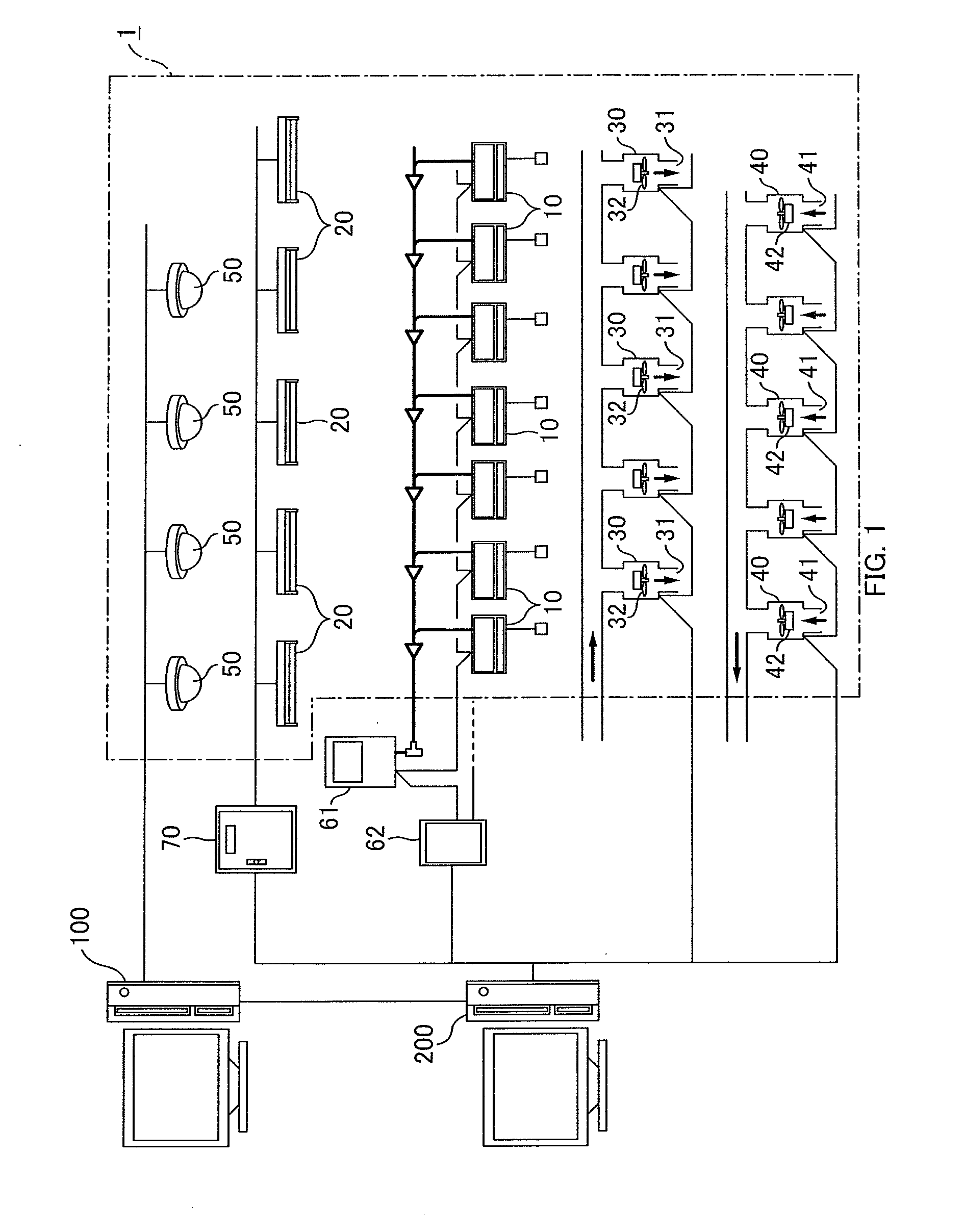
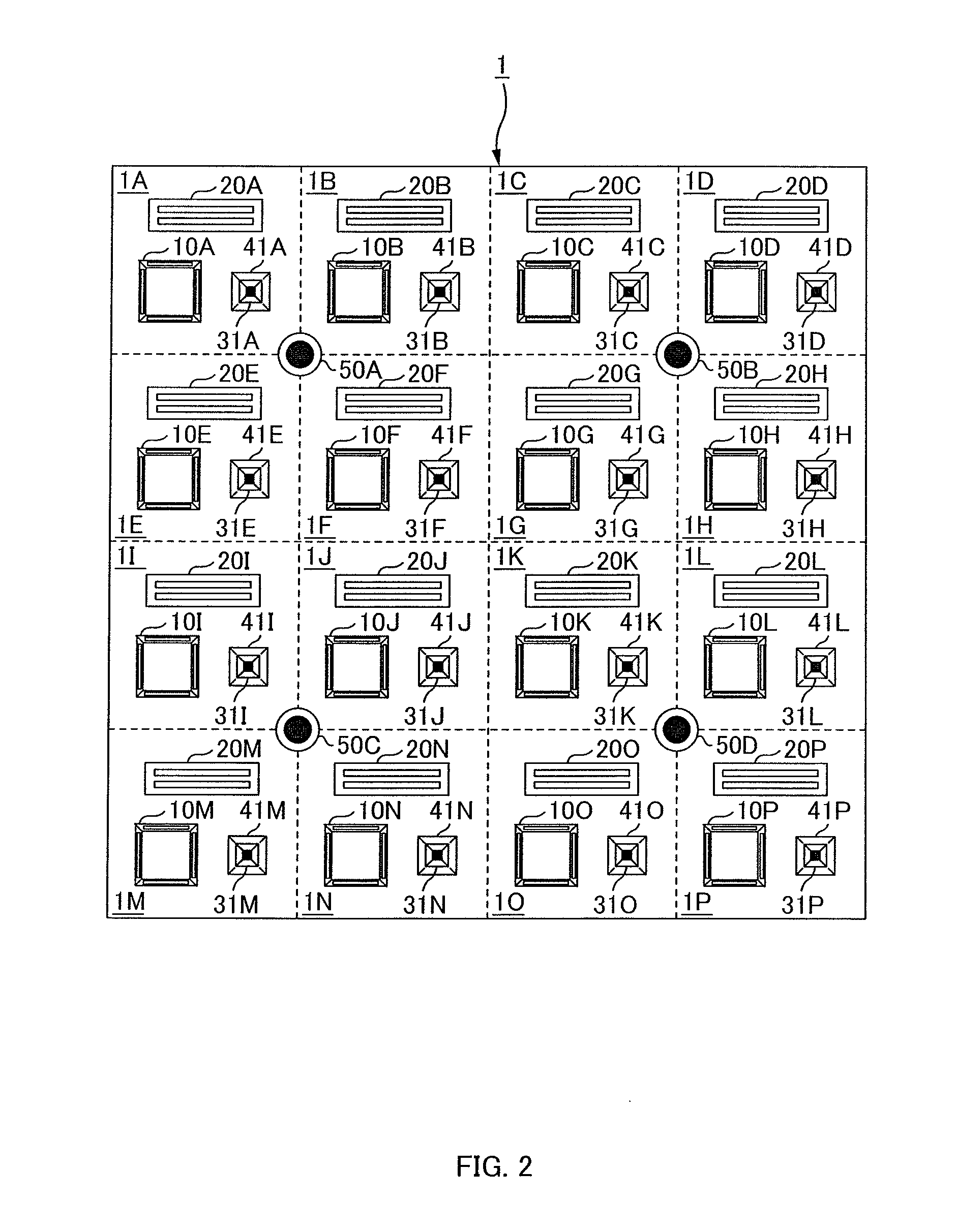
[0029]An electric equipment management system (air-conditioning system, indoor ventilation system) according to an embodiment of the present invention will hereinafter be described. As shown in FIG. 1, this electric equipment management system manages operations of a plurality of types of electric equipment installed in an indoor space 1 (space to be air-conditioned, space to be ventilated) of a building. The electric equipment installed in the indoor space 1 include a plurality of air conditioners 10, a plurality of fluorescent lamp units 20 (illumination units), a plurality of air intake devices 30, a plurality of exhaust devices 40, and a plurality of cameras 50, for example. Further, the building is provided with an outdoor unit 61 and a communication adaptor 62 for the air conditioners 10, an illumination interface 70 for the florescent lamp units 2...


PUM


Abstract

A ventilation control apparatus of an indoor ventilation system including an intake device configured to take outside air into an indoor space, the intake device capable of changing an intake amount of the outside air, the ventilation control apparatus includes: a people count detection unit configured to determine the number of people who are present in the indoor space, to be outputted as people count information; and a control unit configured to obtain the people count information and control the intake device so that the more the number of people indicated by the people count information is increased, the greater an amount of the outside air to be taken in becomes.

Description

CROSS-REFERENCE TO RELATED APPLICATION[0001]This application claims the benefit of priority to Japanese Patent Application No. 2010-019534, filed Jan. 29, 2010, of which full contents are incorporated herein by reference.BACKGROUND OF THE INVENTION[0002]1. Field of the Invention[0003]The present invention relates to a ventilation control apparatus.[0004]2. Description of the Related Art[0005]Such an air conditioner is known that a signal from an image pickup device is processed so that the presence or absence of a human in each control area is determined, and a target temperature of a limit, beyond which people feel uncomfortable, is set in an area where no person is present, while a target temperature lower than a comfortable temperature is set with an air-blow speed being increased to an allowable limit in an area where a person is present (See Japanese Patent No. 3848786, for example).[0006]In the above-described air conditioner, intake of outside air has not been considered at a...

Claims


Application Information

Patent Timeline
Patent Type & Authority Applications(United States)
IPC IPC(8): F24F11/04F24F7/00
CPCF24F2011/0075F24F11/0034F24F11/0001F24F2011/0002F24F11/30F24F2120/10F24F11/46F24F11/77F24F11/64
Inventor YOSHII, KATSUJIOKADA, SHIGERUSEKIGUCHI, KAZUHIRO
Owner PANASONIC INTELLECTUAL PROPERTY MANAGEMENT CO LTD
Learn More