Battery pack for an electric powertrain vehicle

Inactive Publication Date: 2011-08-04
RENAULT SA
View PDF10 Cites 18 Cited by
  • Summary
  • Abstract
  • Description
  • Claims
  • Application Information

AI Technical Summary

Problems solved by technology

It is a problem with the battery pack known from the prior art, to ensure that these requirements are fulfilled for all the modules, especially when the battery packs become large and comprise a large number of modules.

Method used


Image

  • Battery pack for an electric powertrain vehicle
  • Battery pack for an electric powertrain vehicle
  • Battery pack for an electric powertrain vehicle

Examples


first embodiment

[0043]A heat exchanger with its plates indirectly thermally connected with the battery modules by a thermal bridge.

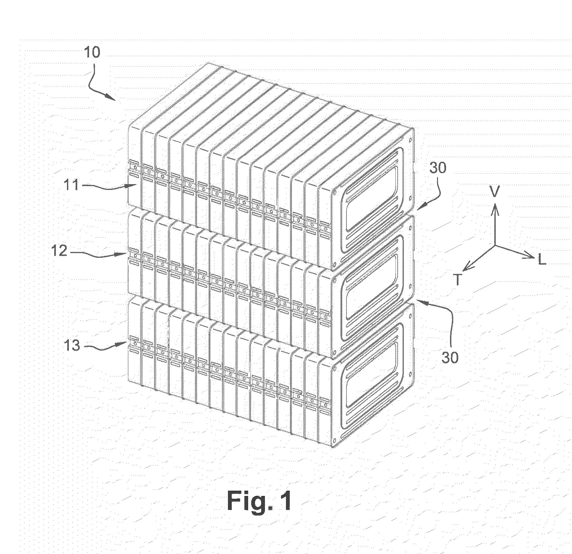
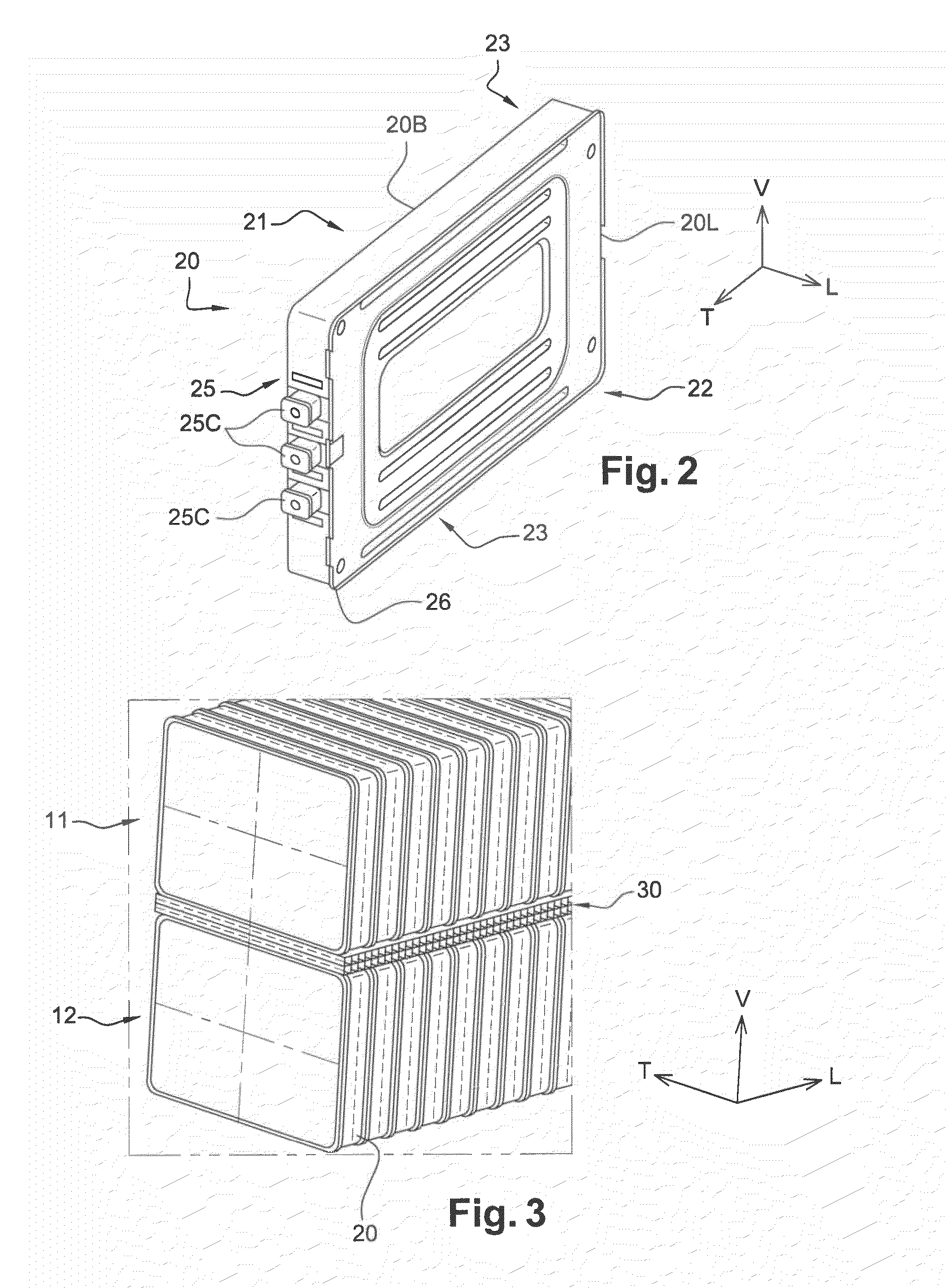
[0044]FIG. 4 depicts the heat exchanger 30 arrangement located in between the first 11 and second 12 stack of battery modules 20 according to a first embodiment of the invention.

[0045]The heat exchanger 30 comprises a first plate 31 indirectly thermally connected to the battery modules of the first stack 11 and a second plate 32 indirectly thermally connected to the battery modules 20 of the second stack 12.

[0046]The plates 31,32 have a rectangular shape and extend in a plan that extends longitudinally and transversally [L-T].

[0047]A plurality of fins 33 connect the first 31 and the second 32 plates to each other. The fins 33 extend vertically and transversally according to plans that are parallel to the vertical and transversal plan [V-T].

[0048]Thus, these fins 33 and plates 31,32 form a plurality of fluid flow ducts 34 in which a fluid, such as air can flow through, i...

second embodiment

[0062]A heat exchanger with its plates directly thermally connected with the battery modules by a thermal bridge.

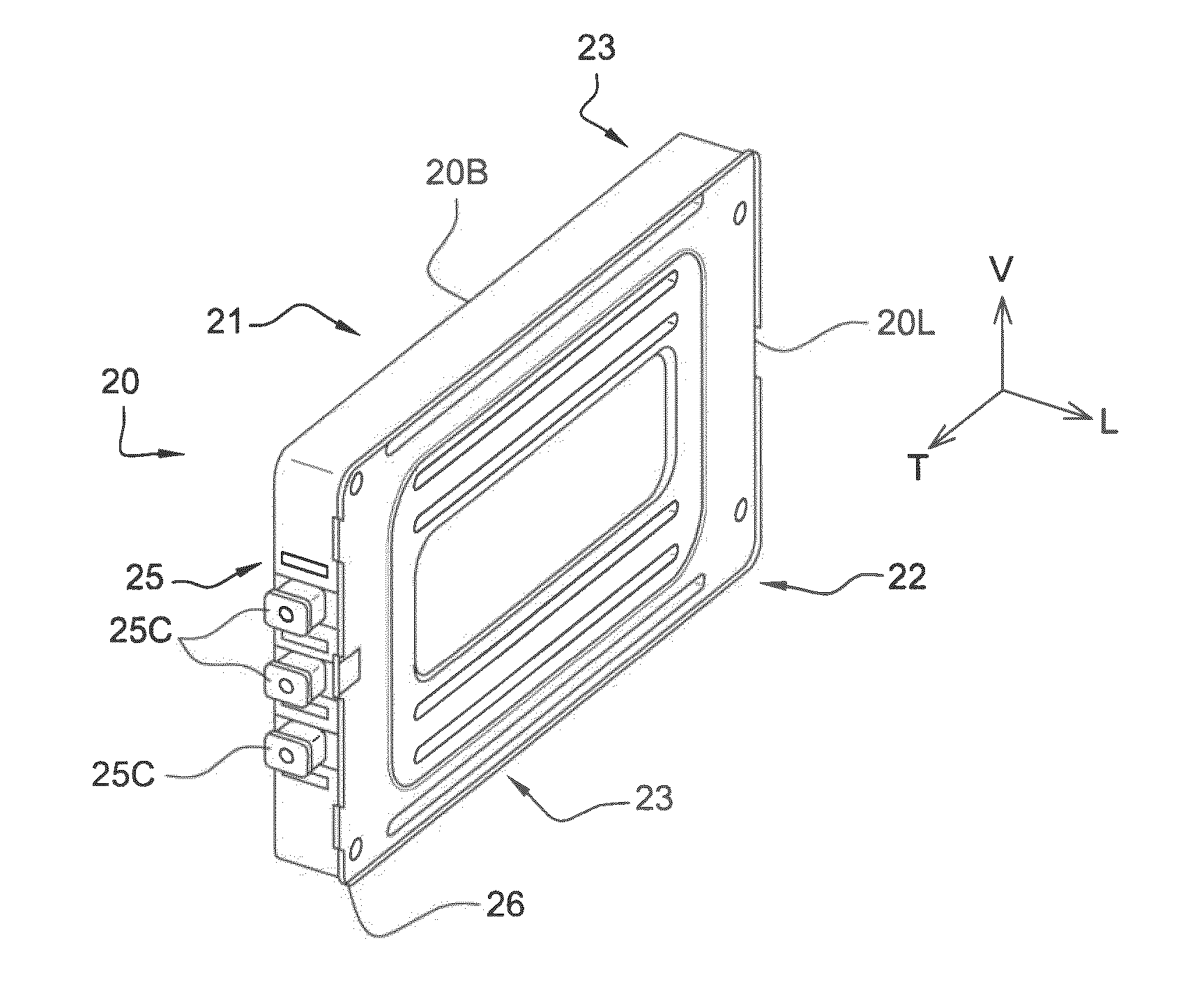
[0063]In a second embodiment of the invention, the plates 31,32 are connected directly with the interstack coupling side faces 23,24 of the battery modules 20.

[0064]According to this second embodiment, the surface treatment of the plates 31,32 and of the interstack coupling side faces 23,24 are optimized to have a perfect matching contact on a surface as large as possible in order to enhance heat transfer and prevent a high resistivity fluid such as air to fill in the space between the plates 31,32 and side faces 23,24.

[0065]For these surfaces to apply on each other, ridges 35 are formed in the plates 31,32 to match with the lip 26 locations on the battery module 20. Thus, the lips 26 are received within these ridges 35 so that the heat exchanger plates 31,32 get into contact with the interstack coupling surfaces 23,24 of the battery modules 20.

[0066]The heat exchanger ac...


PUM

PropertyMeasurementUnit
energyaaaaaaaaaa
energy storage densityaaaaaaaaaa
electrical energyaaaaaaaaaa

Abstract

A battery pack includes at least a first stack of battery modules, and a second stack of battery modules, each stack including a plurality of battery modules arranged in parallel in side by side relationship extending in a longitudinal direction, the battery pack further including at least one heat exchanger interposed between the first and second stacks, the heat exchanger being in thermal contact with interstack coupling surfaces extending in a longitudinal and transversal plan [L-T] of the battery modules. The invention also relates to a corresponding heat exchanger.

Description

FIELD OF THE DISCLOSURE[0001]The present disclosure relates to a heat exchanger for cooling a battery pack of an electric or hybrid vehicle and to a battery pack arrangement with such a heat exchanger.BACKGROUND OF THE DISCLOSURE[0002]Vehicles with at least an electric powertrain, such as electric vehicles or hybrid vehicles, carry a battery pack composed of an array of closely positioned modules, each module being in series with one another, to provide a combined energy of desired level.[0003]To be more compact, to improve energy storage density and to adapt to some particular geometrical spaces, some battery packs comprise a plurality of arrays, or stacks of modules.[0004]During operation, when some electrical energy is transferred in or out from the stacks of modules, during charge and discharge cycles, some heat is produced by the chemical reactions that take place within the modules.[0005]For optimized performance and sustained longevity, the modules have to be maintained durin...

Claims


Application Information

Patent Timeline
Patent Type & Authority Applications(United States)
IPC IPC(8): H01M10/50
CPCH01M10/50H01M10/5046H01M10/5044H01M10/60H01M10/6551H01M10/655Y02E60/10H01M10/613H01M10/625H01M10/6555H01M10/6557H01M10/6556H01M10/647H01M50/20H01M10/6567H01M2220/20
Inventor ALIZON, FRANCK M.MARCHAL, CAROLINEDERUY, DIDIER M.
Owner RENAULT SA
Why Eureka
Try Eureka