
Optical fibers having a Surface Light Field Emulation (s-LiFE) segment and method of making the same

a technology of optical fibers and surface light fields, applied in the direction of fibre light guides, lighting and heating apparatus, instruments, etc., can solve the problems of uncontrollable and interrupted emission of light through the optical fiber length, and undesirable scattering or reflection. , to achieve the effect of reasonable cost and high performance produ

Inactive Publication Date: 2011-08-04
ENLIGHTING
View PDF11 Cites 45 Cited by
  • Summary
  • Abstract
  • Description
  • Claims
  • Application Information

AI Technical Summary

Benefits of technology

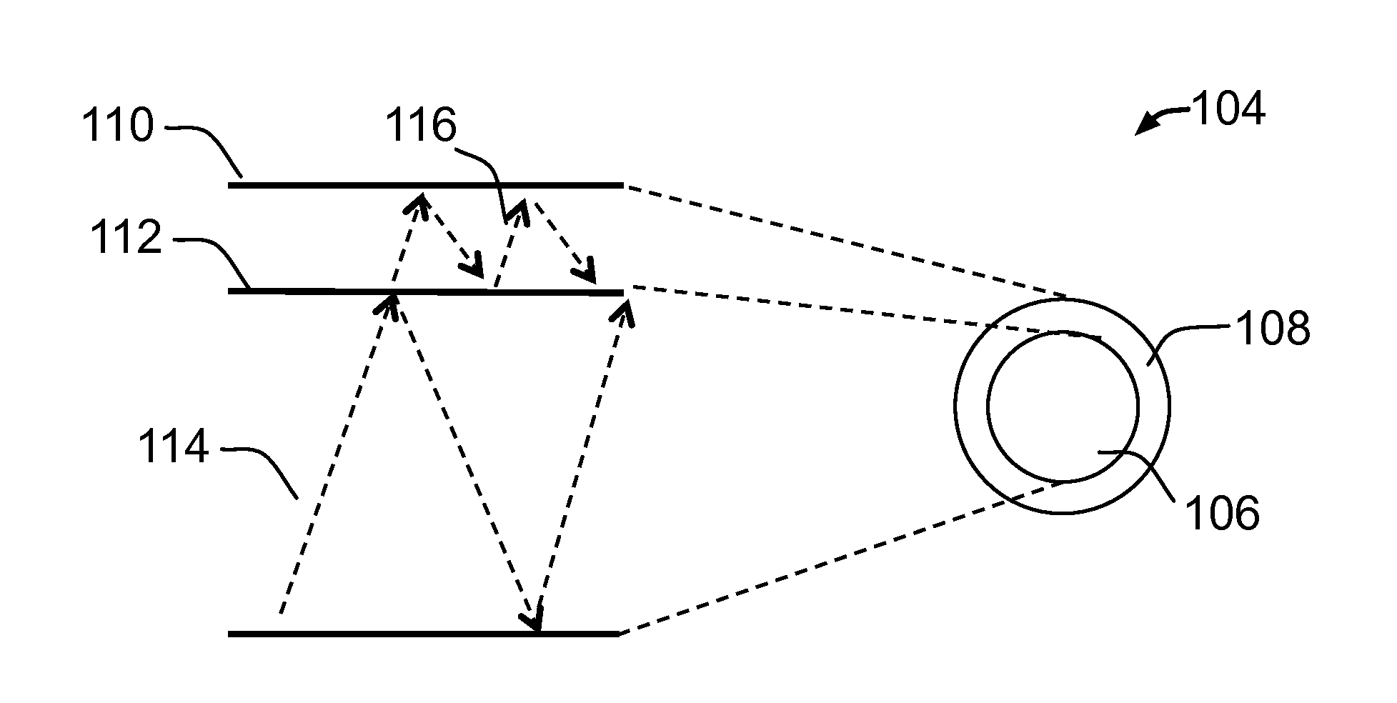
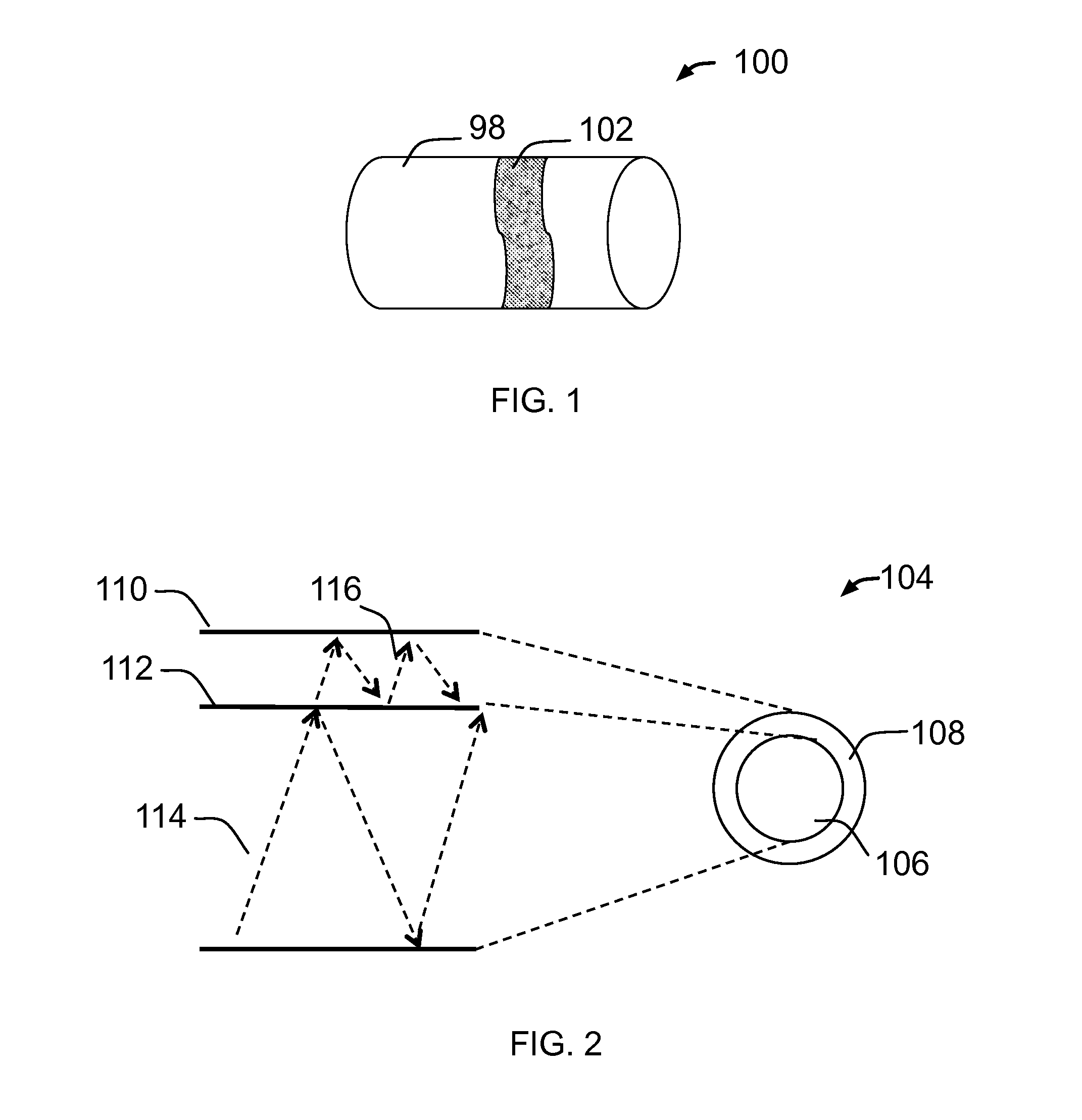
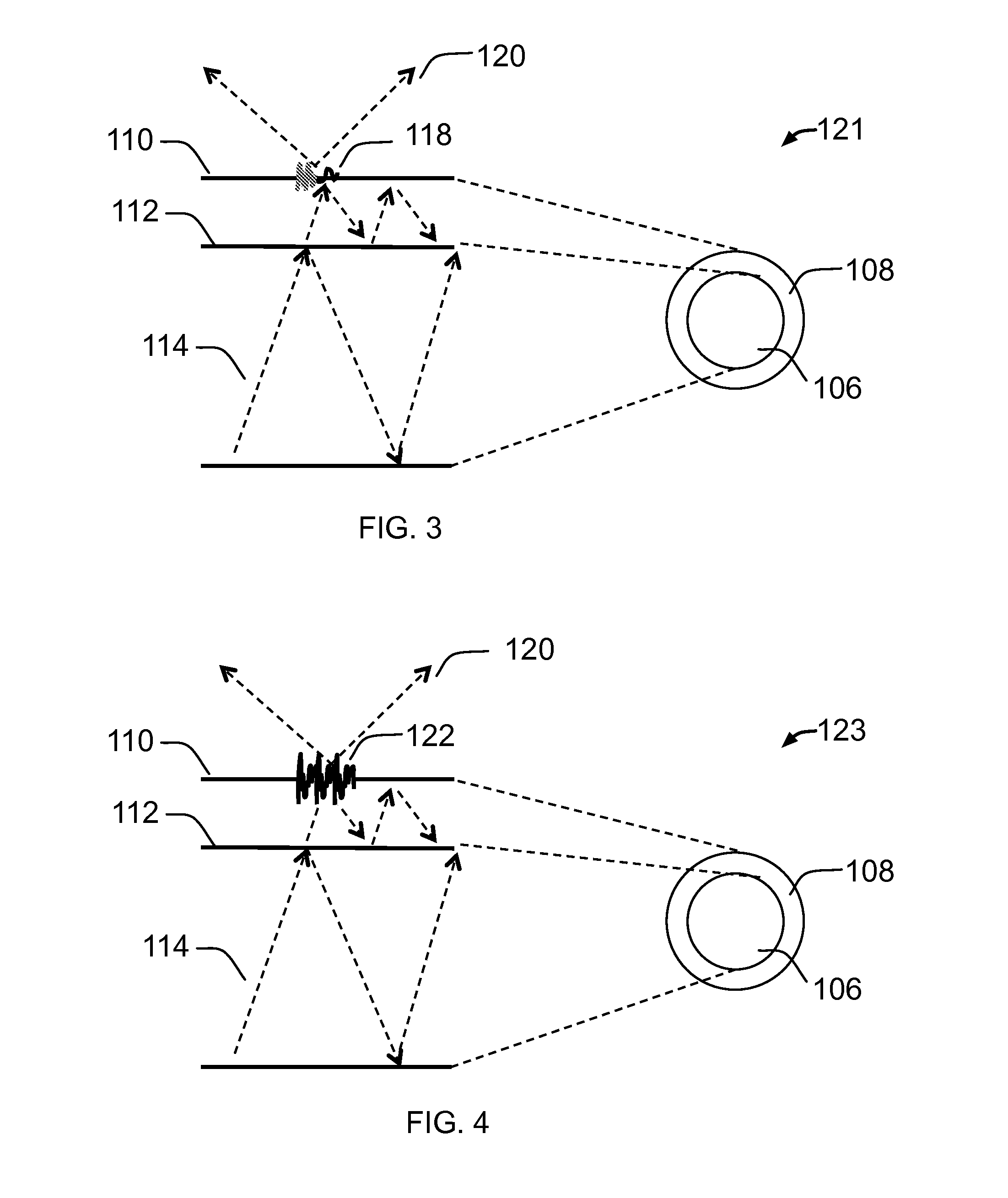
[0017]The present invention provides an optical fiber comprising a Surface Light Field Emulation (s-LiFE) segment. The said Surface Light Field Emulation (s-LiFE) segment comprises at least a core, cladding, and multiple controlled nanoscale diffusion centers. The said nanoscale diffusion centers are capable of changing the light propagation pathway, redirecting and enhancing light coupling from the optical fiber to the exterior environment, and the said light coupling is engineered to provide higher precision control of light emitting properties, such as emission position, intensity, color (wavelength) and visual effects, than that caused by micro-bending, structure deformation and intrinsic impurities in the optical fiber, and without the said nanoscale diffusion centers, the light is strictly confined in the core.
[0054]The choice of materials of the optical fibers, diffusion centers and any coatings will depend upon the light handing properties as well as any requirements from the intended use environment. Careful selection of materials will deliver a high performance product with a reasonable cost.

Problems solved by technology

The micro-bending, surface damaging techniques and using diffuser particles and fluorescent dyes can only achieve uncontrolled and interrupted emission through the optical fiber length.
The additional interfaces will cause undesirable scattering or reflection.
The light extraction overlay and reflector technique are able to achieve carefully engineered emission but the processes are complicated.
The bigger the size of deformations, the more the physical strength and mechanical flexibility of the optical fiber is compromised.

Method used


Image

  • Optical fibers having a Surface Light Field Emulation (s-LiFE) segment and method of making the same
  • Optical fibers having a Surface Light Field Emulation (s-LiFE) segment and method of making the same
  • Optical fibers having a Surface Light Field Emulation (s-LiFE) segment and method of making the same

Examples


Embodiment Construction

[0071]It is to be appreciated that embodiments of the methods and apparatuses discussed herein are not limited in application to the details of construction and the arrangement of components set forth in the following description or illustrated in the accompanying drawings. The methods and apparatuses discussed herein are capable of implementation in other embodiments and of being practiced or of being carried out in various ways. Examples of specific implementations are provided herein for illustrative purposes only and are not intended to be limiting. In particular, acts, elements and features discussed in connection with any one or more embodiments are not intended to be excluded from a similar role in any other embodiments. Any references to embodiments or elements or acts of the systems and methods herein referred to in the singular may also embrace embodiments including a plurality of these elements, and any references in plural to any embodiment or element or act herein may a...


PUM

PropertyMeasurementUnit
refractive indexaaaaaaaaaa
diametersaaaaaaaaaa
distanceaaaaaaaaaa

Abstract

A modified optical fiber comprises one Surface Light Field Emulation (s-LiFE) segment, comprising a core; a cladding; and multiple controlled nanoscale diffusion centers to emit light through the side of the optical fibers. Optionally, the modified optical fiber has a coating. The nanoscale diffusion centers are physical geometric patterns or composition patterns in the cladding or the coating. The s-LiFE optical fiber is a member of an illumination system further comprising a light source. The method of making of said s-LiFE optical fiber comprises a fiber spooning step.

Description

CROSS-REFERENCE[0001]The subject matter as set forth in each one of the following US utility patent applications is incorporated herein by reference in its entirety:[0002]Ser. No. 61 / 300,437 filed Feb. 1, 2010; and[0003]Ser. No. 61 / 333,406 filed May 11, 2010.BACKGROUND[0004]1. Field of Invention[0005]The present invention relates generally to optical fibers with side emissive properties. More particularly, the examples disclosed herein are directed to optical fibers having Surface Light Field Emulation (s-LiFE) properties (herein after “s-LiFE optical fibers”), systems using them and method of making the same. The s-LiFE optical fibers are used for displays or general illuminations and to be produced at a low cost.[0006]2. Discussion of Related Art[0007]Optical fibers are used primarily in the telecommunication industry. An optical fiber typically comprises a core and cladding. The cladding usually has a slightly lower refractive index than that of the core. Light typically strictly...

Claims


Application Information

Patent Timeline
Patent Type & Authority Applications(United States)
IPC IPC(8): G02B6/02G02F1/295G02B6/00
CPCB29D11/00663B82Y20/00G02B6/0003G02B6/0008G02B6/001
Inventor DENG, KUNG-LIOLSON, DANIEL R.YE, QING
Owner ENLIGHTING
Learn More