
Articulated body armour

a technology of body armour and articulation, which is applied in the direction of breathing protection, protective garments, clothing, etc., can solve the problems of increasing fatigue, affecting restricting the free movement of clothing, so as to improve the overall performance of the wearer, less physiological stress, and less restrictive movement

Inactive Publication Date: 2011-08-04
LEWIS CHRISTOPHER MARK
View PDF101 Cites 9 Cited by
  • Summary
  • Abstract
  • Description
  • Claims
  • Application Information

AI Technical Summary

Benefits of technology

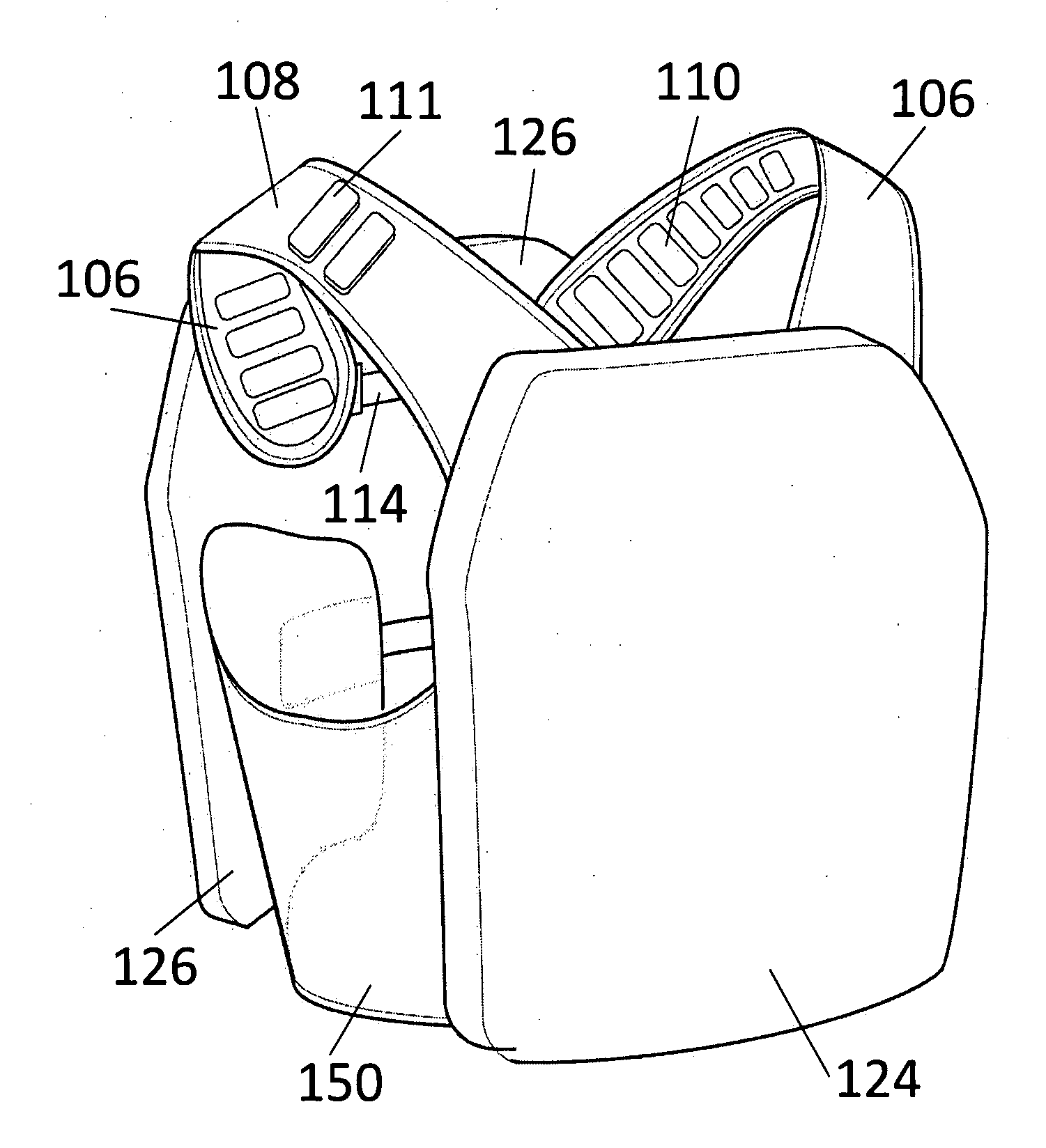
[0015]In overview, the present invention provides an articulated and modular system of body armour in which components are able to rotate about fixings that hold the components together. Some joints allow pivotal and / or linear movements of one component relative to another, e.g. a spherical ball and socket joint or a peg and running slot. By having modular sections of soft armour (or its functional equivalent) in the upper harness 102 and lower girdle 104, the present invention makes use these modular panels to effect a spacing away of the body armour from the wearer's body; this aids in air circulation and heat control. The use of webbing and adjustable straps permits the lengths and / or angles of the various modular components to be altered in relation to each other. The elastic elements connecting the modular panels and plates also allow the body armour to flex so that the wearer is free to twist their torso at times when the wearer is looking backwards or when kneeling down in the firing position.
[0016]The present invention advantageously provides a modular body armour system that is articulated in a way that permits the armour to roll with the movement of its wearer. In this way, the body armour is less restrictive of movement. By providing for chest expansion through an elasticated connection within the shoulder harness and lower girdle of the body armour, a wearer is placed under less physiological stress during times of exertion and mental stress, thereby improving the overall performance of the wearer.

Problems solved by technology

In building up the layers, the resultant garment tends to be very stiff and restrictive of free movement.
Clearly, greater protection is achieved through the use of large plates of hard armour, although this has a drawback in that the plates are both relatively heavy and cumbersome and thus increase fatigue and interfere with a wearer's mobility (even more so than that of soft armour).
U.S. Pat. No. 6,892,392 shows a body armour system with overlapping front or rear plates allowing some increased movement when bending forwards, however this system does not allow for the free independent movement of the shoulders, hips and torso when in the standing or kneeling positions.
However, like other prior art systems, the combination of bulk in the soft armour and heavy plating restricts overall movement for the wearer.
Unfortunately, the selective ability to remove hard armour to benefit from increased mobility compromises the wearer's overall degree of protection.
Conversely, any restriction of a wearer's ability to move into an effective offensive position or take up a protective position (e.g. behind a wall) compromises the wearer's ability to function or otherwise exposes the wearer as a larger target from either delaying or inhibiting the taking up of a defensive posture.
Likewise, the current construction of multi-layered soft armour and its resulting bulk is also not ideal.

Method used


Image

  • Articulated body armour
  • Articulated body armour
  • Articulated body armour

Examples


Embodiment Construction

[0032]Referring to FIG. 1 there is shown an exploded view of prior art body armour system 20 in accordance with WO 03 / 027600. Essentially, left hand and right hand side panels 22, 24 (made from soft armour) are coupled together using front 26 and rear 28 hard armour plates that align and marginally overlap with edges of (and affix to) the side panels 22, 24. The front plate 26 may include overlapping plates 26a, 26b, if desired, to extend the overall amount of torso protection. The side panels 22, 24 include integrally formed shoulder straps 30, 32 that loop over from the rear to permit attachment 36 to a front-side flank to form holes 40, 42 through which a wearer may extend their arms. Foam pads 44, 46 are positioned against an inner surface of the soft armour to effect spacing of the soft armour from the body of a wearer.

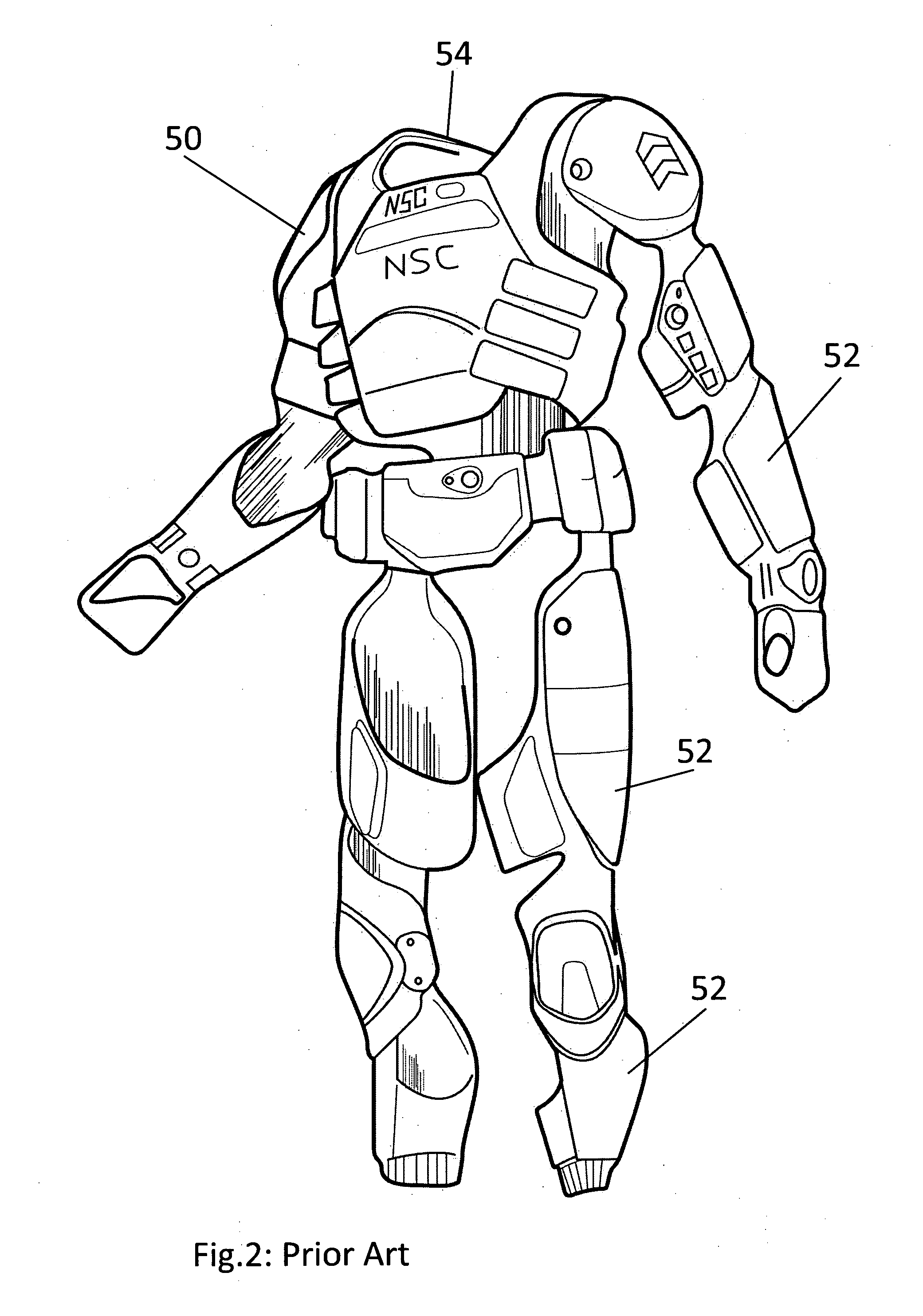
[0033]In FIG. 2 an all-over body armour system 50 is shown. In what can best be described as a Star Wars “Stormtrooper” approach, a rigid exoskeleton made up of ...


PUM


Abstract

A modular body armour system (100) includes an upper shoulder harness (102) in which shoulder straps (106, 108) are pivotally rotatable relative to each other and also to front and back connecting bridges (112, 114) that define a closed loop for the harness (102). Armour plates (124, 126) are attachable to the bridges (112, 114) and extend generally downwardly to protect the front and back torso regions of a wearer of the body armour (100). Pivotal articulation of the body armour (100) permits the armour to roll advantageously with the movement of its wearer such that movement, such as crouching or the adoption of a firing position, is not generally restricted. A lower girdle (104) incorporates additional plates and panels (140, 142, 105, 152) to provide enhanced protection to the wearer, which lower girdle (104) may be entirely independent of the upper shoulder harness (102). By providing for chest expansion through an elasticated connection within both the shoulder harness (102) and the lower girdle (104), a wearer is placed under less physiological stress during times of exertion and mental stress, thereby improving the overall performance of the wearer.

Description

FIELD OF THE INVENTION[0001]This invention relates, in general, to body armour that provides a protective shield against general bodily injury or acute trauma. More particularly, but not exclusively, the present invention relates to personal body armour that can provide ballistic protection against projectile threats, such as high velocity rifle rounds.SUMMARY OF THE PRIOR ART[0002]Security personnel, including policemen, infantry soldiers and special operations forces, are often now equipped with tactical protection in the form of body armour or protective vests to mitigate injury from attack. Such body armour is available in a variety of forms to address varying levels of potential threat, e.g. from bullets and knives.[0003]So-called “soft armour” is worn in the form of jackets and vests and is composed of assemblies of ballistic fibres, such as those formed from Kevlar® from the DuPont company. Typically, soft armour will employ fifteen to thirty layers of thin, flexible and tigh...

Claims


Application Information

Patent Timeline
Patent Type & Authority Applications(United States)
IPC IPC(8): A41D13/05A41D13/00
CPCF41H1/02
Inventor LEWIS, CHRISTOPHER MARK
Owner LEWIS CHRISTOPHER MARK
Learn More